Automotive / Car Audio
User Manual for Hifonics Andromeda Series Amplifiers
Comprehensive user manual for Hifonics Andromeda Series amplifiers, including installation guides, wiring diagrams, system tuning, and troubleshooting procedures for Saturn, Mars, Mercury, Pluto, Krypton, Neptune, and Venus models.
Quick answers from the manual
Quick answer
- The Andromeda Series amplifiers feature variable crossovers, diagnostic protection circuits, and support for various system configurations including mono, stereo, and bi-amplified setups. p. 3, 9
Key actions
- Set level controls to minimum before first power-up. p. 10
First start
- Connect power, ground, and remote turn-on. Set level controls to minimum. Turn on head unit, then adjust levels. p. 10
Show 4 more answers Show less
Problems and fixes
Amplifier enters protect mode
Check for shorted speaker leads or DC offset. Turn head unit off and back on to reset.
p. 12Maintenance and reset
- Reset the amplifier by turning the head unit off and back on. p. 12
Technical specifications
| Parameter | Value | Meaning | Pages |
|---|---|---|---|
| Input Sensitivity | 0.2V to 9V | Range for matching head unit output. | p. 3, 9 |
Where to find it in the PDF
- Feature Descriptions p. 3, 9
- Installation Notes p. 10
- Troubleshooting p. 12
Table of contents
Manual images
Click an image to enlargeImportant Information from the Manual
This manual covers the installation, operation, and troubleshooting of the Hifonics Andromeda Series amplifiers. Before beginning, ensure you have the correct amplifier model for your system requirements. Always set all level controls to minimum before the first power-up to prevent damage to speakers. The amplifiers feature built-in diagnostic systems that will shut down the unit in case of shorted speaker leads, DC offset, or overheating.
Amplifier Feature Descriptions
The Andromeda Series amplifiers are equipped with variable crossovers and diagnostic protection circuits. Key features include:
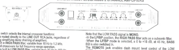
- Crossover Controls: Selectable HI (High Pass), FLAT, or LP/BP (Low Pass/Band Pass) modes.
- Input Sensitivity: Variable from 0.2V to 9V to match head unit output.
- Diagnostic LED: Indicates power status and protection mode.
- Remote Control: The REMOTE jack allows for the addition of the ABR-1 bass remote module for controlling Bass EQ.
Installation Notes
Proper installation is critical for system performance and reliability:
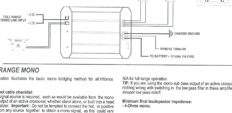
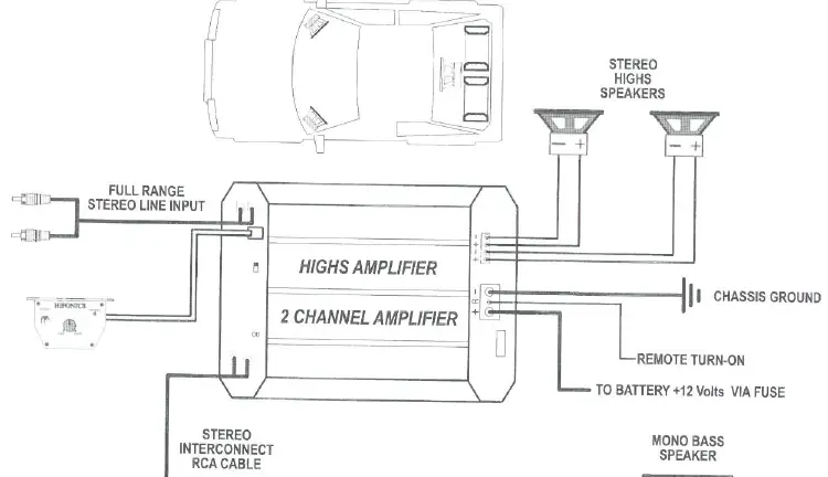
- Mounting: Mount amplifiers with fins running vertically to ensure proper heat dissipation.
- Power and Ground: Use at least 8-gauge power cable. Ground each amplifier directly to the vehicle chassis using a short lead (no more than 12 inches).
- Wiring: Keep RCA cables at least 18 inches away from power and speaker cables to minimize electrical noise.
- Sequence: Connect speaker wires, then RCA cables, then power/ground/remote. Finally, connect the main +12V cable to the battery.
System Setup and Tuning
To achieve the best performance after installation:
- Insert a reference CD and set the head unit volume to approximately 80%.
- Turn the amplifier level control up slowly until distortion is audible, then back off slightly.
- Adjust crossover frequency controls to match your loudspeaker manufacturer's specifications.
- Use the equalizer controls to adjust the system frequency response to your personal taste.
Troubleshooting
If the system is not performing correctly, follow these steps:
- Amplifier Shuts Down: Check for shorted speaker leads or DC offset. Reset by turning the head unit off and back on.
- Overheating: The amplifier will shut down if the heatsink reaches 80°C. Ensure proper airflow and check that speaker impedance is not too low.
- Noise/Hiss: Lower the amplifier level controls. If noise persists, check RCA cable routing and ensure the head unit is properly grounded.
- System Does Not Turn On: Check all fuses, ground connections, and verify +12V and remote turn-on voltage at the amplifier terminals.
Practical help
Common problems
Amplifier enters protect mode
Check for shorted speaker leads or DC offset. Turn the head unit off and back on to reset the diagnostic system.
Amplifier overheats
Ensure the amplifier is mounted with fins vertical for airflow. Check that speaker impedance is not below the recommended minimum.
Excessive noise or hiss
Lower the amplifier level controls. Ensure RCA cables are routed away from power cables and the head unit is properly grounded.
System does not turn on
Check all fuses, ground connections, and verify +12V and remote turn-on voltage at the amplifier terminals.
Before use
- Ensure all fuses are installed.
- Verify +12V and ground connections are secure.
- Set all level controls to minimum before first power-up.
- Check that speaker impedance matches amplifier requirements (2-Ohms stereo or 4-Ohms mono bridged for most models).
- Ensure RCA cables are routed away from power cables.
Show more Show less
Specs in practice
- Subsonic Filter
- Filters out extremely low frequencies that can damage subwoofers.
- Input Sensitivity
- Range (0.2V to 9V) for matching head unit output level.
Images and diagrams
- Wiring diagrams illustrate connections for power, ground, remote turn-on, and speaker outputs.
- Diagrams show bridging methods for mono and multi-channel configurations.
- Bi-amplified system diagrams show how to use separate channels for highs and bass.
Model compatibility
- Minimum impedance: 2-Ohms stereo or 4-Ohms mono bridged for most models.
- Neptune/Venus models support 1-Ohm loads.
- All models feature variable crossovers.

Manual page author
Michael Turner
Technical manual editor