Automotive / Car Audio
User Guide for Morel Maximo Ultra MKII Car Audio Component Speaker System
A comprehensive user guide for the Morel Maximo Ultra MKII car audio component speaker system. Includes detailed installation instructions, crossover wiring diagrams, mounting procedures for surface and flush installations, active...
Quick answers from the manual
Quick answer
- The Morel Maximo Ultra MKII manual provides wiring diagrams for passive crossovers, mounting instructions for surface and flush installations, and active configuration settings for the 603A model. p. 2, 3, 4
Key actions
- Connect the amplifier to the crossover input and the speakers to the crossover outputs according to the provided diagrams. p. 2
- Perform surface or flush mounting using the provided hardware and following the step-by-step visual guides. p. 3, 4
Technical specifications
| Parameter | Value | Meaning | Pages |
|---|---|---|---|
| Nominal Impedance | 4 ohm | Standard impedance for all models. | p. 4 |
| Power Handling (602/603) | 100W | Continuous power handling. | p. 4 |
| Frequency Response | 50-20,000 Hz | Range of frequencies the speakers can reproduce. | p. 4 |
Show 1 more answers Show less
Where to find it in the PDF
- Parts and Wiring p. 2
- Active Configuration and Surface Mounting p. 3
- Flush Mounting and Specifications p. 4
Table of contents
Manual images
Click an image to enlargeQuick Guide from the Manual
This document provides installation and configuration instructions for the Morel Maximo Ultra MKII car audio component speaker system. It covers the 502, 602, 603, and 603A models. Users should refer to the specific wiring diagrams for their model and follow the mounting procedures carefully to ensure proper fitment and sound quality.
Crossover Connection
The crossover is essential for directing the correct frequencies to the tweeter, mid-range, and woofer drivers. Ensure all connections are made according to the polarity markings (+ and -) on the crossover and the amplifier.
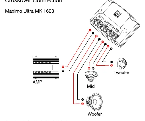
- Maximo Ultra MKII 603: Connect the amplifier output to the crossover input. Connect the tweeter, mid-range, and woofer to their respective terminals on the crossover.
- Maximo Ultra MKII 502 / 602: Connect the amplifier output to the crossover input. Connect the tweeter and woofer to their respective terminals.
Mounting Instructions
Surface Mounting
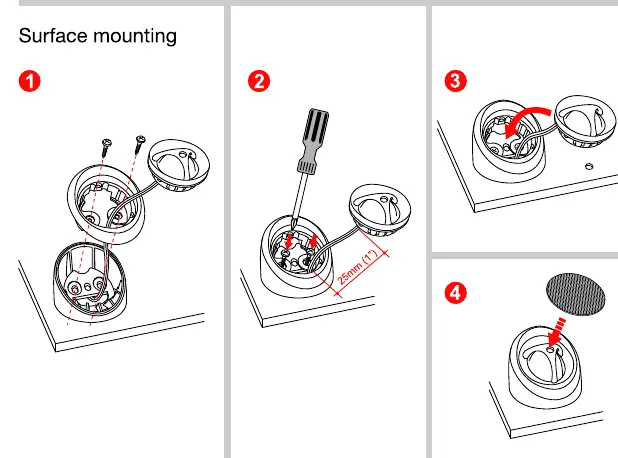
- Prepare the surface area.
- Secure the tweeter housing using the provided screws.
- Route the wires through the housing.
- Attach the grille cover.
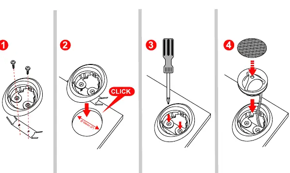
Flush Mounting
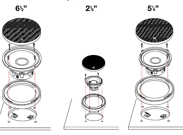
Two options are provided for flush mounting, typically requiring a 50mm (1.96") cutout. Ensure the mounting depth is sufficient for the speaker components before cutting.
Active Configuration (603A)
The Maximo Ultra MKII 603A is an active component set requiring an electronic crossover and six channels of amplification. Recommended crossover points are:
- Tweeter: High-pass filter 4,500Hz @ 12dB
- Midrange: Low-pass filter 4,500Hz @ 12dB; High-pass filter 500Hz @ 12dB
- Woofer: Low-pass filter 500Hz @ 12dB
Specifications
The manual provides detailed technical specifications for the 502, 602, 603, and 603A models, including nominal impedance (4 ohm), power handling (90W-100W), frequency response (50-20,000 Hz), and mounting depths for each driver.
Practical help
Common problems
Incorrect frequency response or sound distortion
Verify that the crossover points are set correctly according to the active configuration guide (for 603A) or that the passive crossover is wired correctly.
Speaker does not fit in the mounting location
Check the mounting depth specifications (e.g., 60mm for 602 woofer) and ensure the cutout diameter is correct before installation.
Before use
- Verify the model number (502, 602, 603, or 603A) to use the correct wiring diagram.
- Check the available mounting depth in your vehicle door or panel.
- Ensure the amplifier is compatible with the 4-ohm nominal impedance.
- Confirm you have all components listed in the 'Content' section (tweeters, woofers, crossovers, screws).
- For 603A active systems, ensure you have a DSP or electronic crossover capable of the recommended filter settings.
Show more Show less
Specs in practice
- Nominal Impedance
- The electrical resistance of the speaker, rated at 4 ohms for these models.
- Power Handling
- The amount of power the speaker can handle continuously (e.g., 100W for 602/603).
- Mounting Depth
- The physical depth required behind the mounting surface to install the speaker.
Images and diagrams
- Crossover Connection: Shows how to wire the amplifier to the crossover and the crossover to the individual drivers.
- Surface Mounting: Step-by-step visual guide for mounting the tweeter on a flat surface.
- Flush Mounting: Step-by-step visual guide for installing the tweeter into a 50mm cutout.
Model compatibility
- The 603A model requires an external electronic crossover or DSP.
- Ensure the amplifier can handle the specific power requirements of the chosen model.

Manual page author
David Miller
Documentation analyst