Tools / Power Tools
HiKOKI G 10SS2 / G 12SS2 / G 13SS2 Disc Grinder Instruction Manual
Official handling instructions for HiKOKI G 10SS2, G 12SS2, and G 13SS2 disc grinders, covering safety, operation, maintenance, and assembly procedures.
Table of contents
Manual images
Jump to the sectionProduct Overview
The HiKOKI G 10SS2, G 12SS2, and G 13SS2 are professional-grade disc grinders designed for removing casting fins, finishing various steel, bronze, and aluminum materials, and grinding welded sections. These tools are powered by a 600W motor and are intended for grinding operations only.
Safety Precautions
Warning: Failure to follow safety instructions can lead to electric shock, fire, or serious injury. Always wear eye protection and use appropriate personal protective equipment (dust mask, gloves, hearing protection). Ensure the work area is clean, well-lit, and free of flammable materials. Do not use the tool in explosive atmospheres.
Operation
Before starting, ensure the power source matches the tool's nameplate specifications. Always verify the switch is in the OFF position before plugging in. The wheel guard must be securely fitted and adjusted to protect the operator from wheel fragments. When grinding, maintain an angle of 15°–30° between the wheel and the workpiece. Do not apply excessive pressure; the weight of the machine is generally sufficient for effective grinding. After switching off, wait for the wheel to come to a complete stop before setting the tool down.
Maintenance
Regularly inspect the grinding wheel for cracks or defects. Check that all mounting screws are tight. Carbon brush inspection and replacement, as well as power cord repairs, must only be performed by a HiKOKI Authorized Service Center to ensure safety. Keep air vents clear of dust to prevent motor overheating.
Manufacturer information
HiKOKI
Practical help
Common problems
Tool does not start or stops unexpectedly
Check power source, ensure switch is in the correct position, and verify the push button is disengaged.
Excessive vibration during operation
Stop immediately, check if the grinding wheel is correctly mounted, tightened, and free of defects.
Wheel digging into workpiece
Ensure the grinding angle is 15°–30° and draw the grinder across the workpiece toward the operator during initial use.
Before use
- Verify power source matches tool specifications.
- Ensure the power switch is in the OFF position.
- Check that the wheel guard is securely fitted and adjusted.
- Inspect the grinding wheel for cracks or surface defects.
- Confirm the wheel nut is securely tightened.
- Perform a 30-second no-load trial run in a safe position.
Specs in practice
- Peripheral Speed
- 72 m/s (G10SS2) or 80 m/s (G12SS2/G13SS2); critical for wheel safety.
Images and diagrams
- Fig 1: Shows how to fit and adjust the wheel guard using the setting screw.
- Fig 2: Illustrates the installation of the side handle into the gear cover.
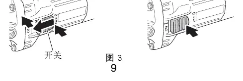
- Fig 3: Demonstrates the slide switch operation (ON/OFF latching).
- Fig 4: Displays the correct 15°–30° grinding angle and direction of movement.
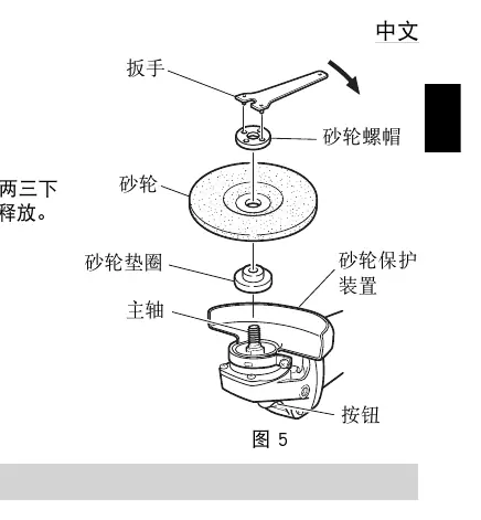
- Fig 5: Details the assembly sequence of the wheel washer, depressed center wheel, and wheel nut.
Model compatibility
- Do not use cutting-off wheels for side grinding.
- Do not use separate reducing bushings or adapters for large hole wheels.
- Ensure threaded hole wheels have sufficient thread length for the spindle.

Manual page author
David Miller
Documentation analyst
Organizes user manual content into clear summaries, with attention to model details, product context, and everyday usability.