Electronics / Projector Screens
Hisense 120L5F Laser Cinema Display Screen Installation Guide
A comprehensive installation and assembly guide for the Hisense 120L5F Laser Cinema Display Screen. This manual covers frame assembly, screen material handling, wall mount installation for various wall types, and maintenance instructions.
Table of contents
Manual images
Click an image to enlargeQuick guide from the manual
This guide provides instructions for assembling and installing the Hisense 120L5F Laser Cinema Display Screen. Key requirements include a clean, flat assembly area of at least 3.5m x 2.5m. Always wear the provided white gloves when handling the screen material to prevent damage. Do not use solvents like alcohol or acetone for cleaning. Ensure the frame is perfectly square during assembly to avoid screen distortion.
Product Description and Maintenance
The screen features a bezel trim designed for rooms where ceiling light cannot be moved. To maintain the screen, wipe only from left to right; do not wipe up and down or in a circular motion. Use a soft brush or microfiber cloth. Never touch the screen material with bare hands, as fingerprints are difficult to remove and may damage the surface.
Required Tools and Parts
Before starting, ensure you have the following tools: tape measure, stud finder, level, pencil, drill with 5/16" (8mm) bit, hammer, Phillips screwdriver, and tape. Verify all hardware components, including screws (ST5.5x70, M3x6, M3x7), bracket wands, hanging components, and the paper template, are present as listed in the hardware inventory.
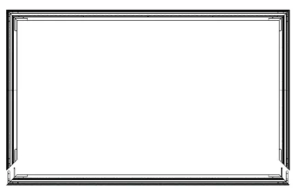
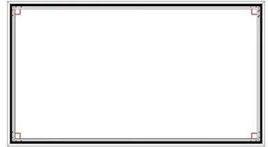
Frame Assembly
1. Place the cloth liner on a clean surface. 2. Insert the L corner pieces and L elbow joints into the ends of the long inner frames. 3. Connect the short inner frames to the corner pieces. 4. Fasten all four corners with M4x6 screws to ensure a perfect square. 5. Mount the vertical beam to support the frames using M3x7 screws.
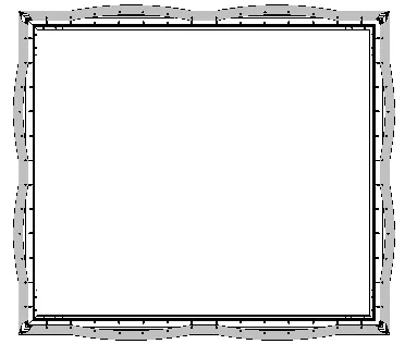
Screen Material Installation
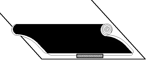
1. Place the reflecting screen material on a clean surface with the front side facing down. 2. Use the provided white gloves. 3. Place the assembled frame on top of the material. 4. Align the corners carefully. 5. Use the spring hook tool to attach springs to the holes on the outer edge of the material. Start by attaching the four corners, then follow the numbered sequence (1-1, 2-2, etc.) to ensure even tension across the screen.
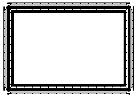
Outer Frame Installation
1. Place the outer frame pieces along the edges of the screen material. 2. Adjust the trim so top and bottom pieces touch with no gaps in the center. 3. Secure the outer frame using M3x7 screws and L corner fittings. Do not overtighten the plastic corner fittings; the proposed force is less than 0.3 N.M.
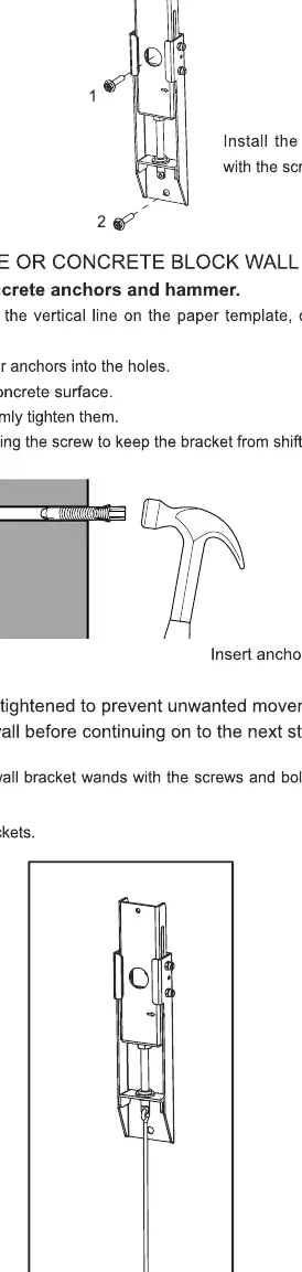
Wall Mount Installation
1. Use the paper template to mark the height on the wall. 2. For drywall with wood studs, use a stud finder to locate studs and drill holes for the screws. 3. For solid concrete or concrete block walls, drill holes and insert anchors. 4. Attach the wall bracket wands to the wall mounts. 5. Ensure the brackets are firmly tightened before hanging the screen.
Hanging the Screen
1. With two people, lift the assembled screen and place it onto the wall brackets. 2. Use the velcro strips on the bottom of the screen to secure it to the wall. 3. Adjust the height of the screen by rotating the wands on the brackets. 4. Once leveled, fold and rest the wands on the screen bracket at the bottom.
Manufacturer information
Hisense
Practical help
Common problems
Screen material damaged or marked
Always wear the provided white gloves. Do not touch the material with bare hands or sharp objects. Do not use solvents like alcohol, acetone, or benzene.
Screen surface is uneven or distorted
Ensure the frame is a perfect square during assembly. When attaching springs, follow the specific numbered sequence to maintain even tension.
Material orientation is incorrect
Check for the 'DOWNSIDE' label on the material. Ensure the black side is facing the front before mounting.
Before use
- Verify all parts (frames, screws, springs) are present.
- Prepare a clean, flat assembly area (min 3.5m x 2.5m).
- Wear the provided white gloves.
- Check wall type (drywall with studs vs. concrete).
- Ensure you have a stud finder, level, and drill.
Specs in practice
- Installation space
- Minimum area required is 3.5m x 2.5m.
- Viewing distance
- Recommended minimum distance is 177 inches (4.5m).
- Concrete wall thickness
- Minimum 8 inches (203mm) required for secure mounting.
Images and diagrams
- Spring hook sequence: Attach corners first, then follow the numbered sequence (1-1, 2-2, etc.) to ensure even tension.
Model compatibility
- Not recommended for ceiling mounting of the laser console.

Manual page author
Emily Carter
User documentation editor
Prepares concise manual descriptions and highlights the most useful setup, operation, and maintenance information for readers.