Electronics / Projector Screens
Installation Guide for Hisense 120L9H Laser TV Screen
A comprehensive installation and setup guide for the Hisense 120L9H Laser TV Screen. Includes detailed instructions for frame assembly, screen material mounting, wall bracket installation, and screen adjustment.
Table of contents
Manual images
Click an image to enlargeImportant Installation Information
Before beginning the installation, ensure you have a clear space of at least 3.5m x 2.5m. The screen material is delicate; always wear the provided white gloves to prevent fingerprints, dust, or oil from damaging the surface. Do not touch the material with bare hands or sharp objects. The screen material has a specific orientation; if it appears white, turn it around, as the correct side is black.
Required Tools
- Tape measure
- Stud finder
- Level
- Pencil
- Screwdriver with 5/16" (8mm) drill bit for wood studs
- Hammer for concrete anchors
- Phillips screwdriver
- Tape
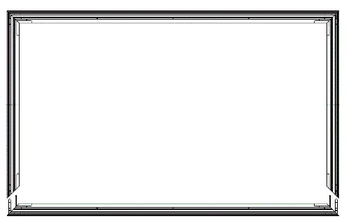
Frame Assembly
Assemble the inner frame by connecting the Long Inner Frames (A1, A2) using Connectors (Q, R) and M4x6 Screws (E). Insert the L Corner Pieces (C) and L Elbow Joints (D) into the ends of the frame. Connect the Short Inner Frames (B) to the corners and fasten all angles with M4x6 Screws (E). Ensure the frame forms a perfect square. Finally, mount the Vertical Beam (O) at the joint of the long frames using M3x7 Screws (N).
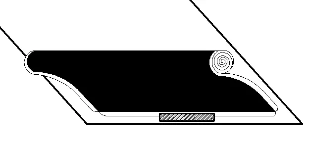
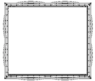
Screen Material Installation
Lay the screen material face down on a clean surface. Unroll the material carefully with two people to avoid bending. Place the assembled frame on top of the material. Attach the springs using the Spring Hook (K), starting with the four corners in the order 1-1 to 4-4, then 5-5 to 8-8. Ensure the material is stretched evenly and is not stretched out of the frame.
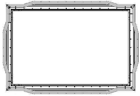
Outer Frame Installation
Connect the Long Outer Frames (L1, L2) using Connector (S) and M3x7 Screws (N). Place the outer frame along the edges of the screen material, ensuring the L1 frame with the logo is at the bottom right. Align the trim pieces so there are no gaps and fasten them using M3x7 Screws (N). Secure the corners with the L Corner Fitting (P), using a force of less than 0.3 N.M to avoid slipping.
Wall Mount Installation
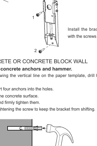
Determine your wall type (drywall with studs or solid concrete). Mark the height on the wall (73 inches above the TV stand). Use the paper template to mark the drilling locations. For wood studs, use a stud finder to locate the center of the studs. For concrete, drill holes and insert anchors. Install the brackets firmly. Connect the wands to the brackets as shown in the manual.
Hanging and Adjusting the Screen
With two people, hang the screen onto the wall brackets. Attach the handles to the wands to adjust the screen height. Rotate the wands clockwise to move the screen down or counter-clockwise to move it up. Once level, fold the wands and rest them on the bottom bracket. Finally, remove the release paper from the velcro strips and push the screen against the wall.
Maintenance and Safety
Clean the screen surface only with a soft brush or microfiber cloth. Wipe from left to right only; do not wipe up and down or in a circular motion. Do not use organic solvents like acetone, benzene, or alcohol. WARNING: Do not look directly at the laser lens when the device is on, as the laser light may damage your eyes.
Manufacturer information
Hisense
Practical help
Common problems
Screen material appears white
The material is facing the wrong way. Turn the screen around; the correct side is black.
Screen is not level
Use the wands to adjust. Rotate clockwise to lower the screen, or counter-clockwise to raise it.
Screen material damaged or marked
Always use the provided white gloves. Do not touch with bare hands, point with sharp objects, or use organic solvents.
Before use
- Ensure installation space is at least 3.5m x 2.5m.
- Wear the provided white gloves to handle the screen material.
- Verify all parts (frames, connectors, screws) are present.
- Have a stud finder, level, tape measure, and drill ready.
- Ensure two people are available to handle the screen.
Specs in practice
- Installation Space
- Minimum 3.5m x 2.5m required for assembly and mounting.
- Viewing Distance
- Recommended minimum distance of 4.5m (177 inches) for optimal experience.
- L Corner Fitting Torque
- Tighten screws with less than 0.3 N.M force to prevent plastic fitting slippage.
Images and diagrams
- Frame assembly uses specific connectors (Q, R, S) and screws (M4x6, M3x7).
- Spring attachment follows a specific 1-8 sequence to ensure even tension across the frame.
- Wand rotation controls the vertical height of the screen.
Model compatibility
- Compatible with drywall with wood studs.
- Compatible with solid concrete or concrete block walls.

Manual page author
Emily Carter
User documentation editor
Prepares concise manual descriptions and highlights the most useful setup, operation, and maintenance information for readers.