Industrial / Gas Detection
Safety Manual for Honeywell Searchpoint Optima Plus Gas Detector
Comprehensive safety and proof test guide for the Honeywell Searchpoint Optima Plus gas detector. Includes detailed inspection procedures, bump testing, re-zeroing, and 4-20 mA loop testing instructions for various communication interfaces.
Table of contents
Manual images
Click an image to enlargeImportant Information
The Searchpoint Optima Plus requires a proof test interval of 1 year to maintain its safety parameters. Users may extend this interval according to IEC 61508 if proper calculation methods are followed. Note that the HART Communications and RS485 link must not be used for safety purposes.
Safety Parameters
- SFF: > 90%
- PFDavg: 2.6x10^-4
- PFH: 5.8x10^-8
Inspection and Maintenance
Regular inspection and cleaning are required. Always inhibit the 4-20 mA output signal before starting maintenance to prevent false alarms. If using a multimeter to monitor the output, power off the unit first to avoid latched warnings.
Cleaning Procedures
- Standard Weather Protection: Remove retaining nuts, inspect for debris, clean or replace the dust barrier, and clean optics with mild detergent and a soft cloth.
- Flow Housing: Disconnect pipework, remove retaining nuts, slide off the housing, and clean optics. Ensure O-rings are clean and in good condition before reassembly.
Proof Test Procedures
The manual provides specific instructions for performing proof tests using three different methods:
- SHC1 Handheld Interrogator: Includes inspection, re-zeroing, bump testing, and 4-20 mA loop verification.
- HART Communications: Includes device setup, inhibition, inspection, re-zeroing, bump testing, and mA loop testing.
- XNX Universal Transmitter: Includes specific inspection steps and integration with the XNX system.
Bump Test (Gas Challenge)
Functionally check the unit using an appropriate test gas. Ensure the unit has been powered up for at least 1 hour before testing. Apply test gas, verify the response, and ensure the reading returns to zero after removing the gas source.
Manufacturer information
Honeywell International Inc.
Practical help
Common problems
4-20 mA loop warning after maintenance
Perform a Soft Reset or Device Reset to clear latched warnings caused by disconnecting a multimeter.
False gas readings during maintenance
Always inhibit the 4-20 mA output signal before starting inspection or cleaning procedures.
Flow housing difficult to remove
The housing may require force due to O-ring friction; ensure O-rings are clean and in good condition upon reassembly.
Before use
- Ensure unit is powered up for 1 hour before gas testing.
- Inhibit 4-20 mA output signal before inspection.
- Use mild detergent and soft cloth for optics cleaning; avoid solvents.
- Verify O-rings are clean and intact when reassembling flow housing.
- Ensure unit is not left in Inhibit mode after testing.
Show more Show less
Images and diagrams
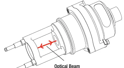
- Optical beam path for inspection
- Standard weather protection assembly
- Flow housing assembly
Model compatibility
- HART Communications and RS485 link must not be used for safety purposes.
- Compatible with SHC1 Handheld Interrogator.
- Compatible with XNX Universal Transmitter.

Manual page author
Michael Turner
Technical manual editor