Industrial / Gas Detection
Instruction Manual for Honeywell Sensepoint PPM Combustible Sensor
Quick guide for the Honeywell Sensepoint PPM Combustible Sensor. Includes installation, wiring, calibration procedures, troubleshooting, and maintenance instructions.
Quick answers from the manual
Quick answer
- The Sensepoint is a sealed disposable sensor for detecting flammable gases. It requires a 2.9V-3.5V power supply, 20-minute warm-up, and must be installed in an approved Ex e or Ex d junction box. p. 1, 2
Key actions
- Remove the protective disc before installation. p. 2
- Calibrate the sensor using a target gas. p. 2
First start
- Allow 20 minutes for warm-up. p. 1, 2
Show 4 more answers Show less
Problems and fixes
Sensor reads zero when gas is applied
Check wiring, remove dust cap, check sinter, or replace sensor.
p. 2Maintenance and reset
- Change the filter by removing the black plastic retainer. p. 2
Technical specifications
| Parameter | Value | Meaning | Pages |
|---|---|---|---|
| Operating Temperature | -30°C to +65°C | Standard operating range | p. 1 |
| Voltage | 2.9 V to 3.5 V | Bridge voltage at 200mA | p. 1 |
Where to find it in the PDF
- Specifications and Features p. 1
- Installation and Calibration p. 2
Table of contents
Manual images
Click an image to enlargeQuick guide from the manual
The Honeywell Sensepoint is a sealed, disposable sensor designed for detecting flammable gases. It is intended for use in hazardous areas and must be installed in an approved Ex e or Ex d junction box. Key operational requirements include a 20-minute warm-up period, a 2.9V to 3.5V power supply, and regular calibration. Installation and service must be performed by qualified personnel.
Description and features
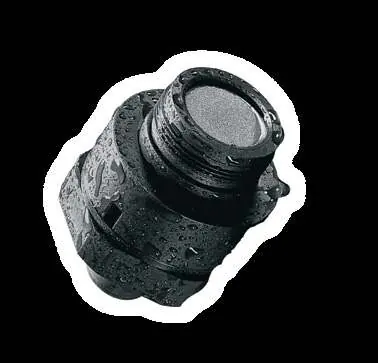
The Sensepoint sensor utilizes a catalytic pellistor device within a bridge measuring circuit. It is certified for hazardous areas to EN60079 and provides IP65 protection (IP67 with weather protection). The sensor is available in M20 or 3/4 NPT thread versions.
Installation
Installation must be performed by a qualified engineer with the power disconnected. Ensure the sensor is installed in a location free from direct heat sources and facing downwards for optimum water protection.
- Protective Disc: Remove the sensor's protective disc before use by unscrewing the filter housing, removing the filter, and discarding the disc. Refit the filter and housing.
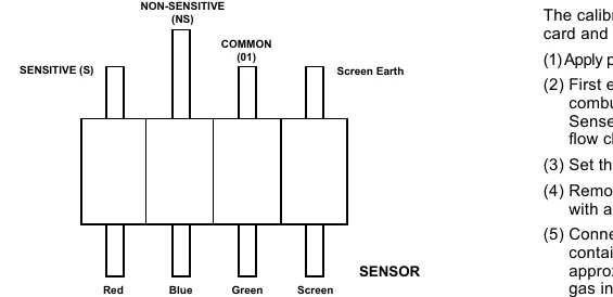
- Wiring: Use three-core multi-strand cable (max 2.5mm² / 14AWG) with a screen. Connect according to the wiring diagram: Red (Sensitive), Blue (Common), Green (Non-Sensitive), Screen (Earth).
- Mounting: Fit into a threaded hole in the junction box and lock with a nut.
Calibration
Calibration should only be performed by qualified personnel. It is recommended to calibrate with the target gas. If not possible, use the cross-calibration formula provided in the manual.
Calibration Procedure
- Apply power and allow 20 minutes for warm-up.
- Ensure no gas is present on the sensor.
- Set the zero reading on the control system.
- Fit a Flow Housing accessory.
- Connect the Flow Housing to a regulated cylinder with a known concentration of target gas.
- Pass gas at 1 to 1.5 litres per minute for 2 to 3 minutes.
- Adjust the control card to indicate the target gas concentration.
Maintenance
The only user-serviceable maintenance is changing the filter.
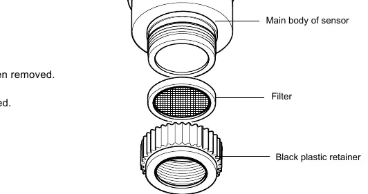
- Remove the black plastic retainer or accessory.
- Remove the old filter and replace it with a fresh one.
- Replace the black plastic retainer or accessory.
Troubleshooting
If the sensor reads non-zero when no gas is present, adjust the zero of the control system. If the sensor reads low or high when gas is applied, adjust the span of the control system. If the sensor reads zero when gas is applied, check the wiring, ensure the dust protection cap is removed, check that the sinter is not obstructed, and replace the sensor if poisoning is suspected.
Specifications
- Operating Temperature: -30°C to +65°C
- Operating Humidity: 20% to 90% RH (continuous)
- Warm-up Time: 20 minutes
- Voltage Range: 2.9V to 3.5V bridge (at 200mA)
- Power Consumption: 700mW
- Calibration Flow Rate: 1 to 1.5 l/min
- Expected Life: 5 years
Manufacturer information
Honeywell International Inc.
Practical help
Common problems
Sensor reads non-zero when no gas is present
Adjust the zero of the control system.
Sensor reads low or high when gas is applied
Adjust the span of the control system.
Sensor reads zero when gas is applied
Check wiring, ensure dust cap is removed, check that the sinter is not obstructed, or replace the sensor if poisoning is suspected.
Before use
- Ensure installation is performed by a qualified engineer.
- Remove the protective disc from the sensor before use.
- Ensure the junction box is Ex e or Ex d certified.
- Verify the power supply is 2.9V to 3.5V (200mA).
- Allow 20 minutes for warm-up before calibration.
Show more Show less
Specs in practice
- Operating Temperature
- -30°C to +65°C
- Warm up time
- 20 minutes required for stabilization.
- Voltage range
- 2.9 V to 3.5 V bridge (at 200mA).
Images and diagrams
- Wiring: Red (Sensitive), Blue (Common), Green (Non-Sensitive), Screen (Earth).
Model compatibility
- Requires approved Ex e or Ex d junction box.
- Compatible with M20 or 3/4 NPT threads.

Manual page author
Emily Carter
User documentation editor