HVAC / Parts & Accessories
Installation and Wiring Guide for Honeywell 7800 SERIES 22-Terminal Universal Subbase
Comprehensive installation and wiring guide for the Honeywell 7800 SERIES 22-Terminal Universal Subbase. Includes critical compatibility details for 1000 and 2000 series relay modules, mounting instructions, wiring requirements, and safety...
Quick answers from the manual
Quick answer
- The Q7800 series is a universal wiring subbase for 7800 SERIES Relay Modules. It is critical to match the subbase version (1000 vs 2000 series) with the correct Relay Module. 2000 series modules require a specific Grounding Pin to operate. p. 1, 2, 3
Key actions
- Mounting p. 5, 6
Problems and fixes
2000 Series module not working
Check if Grounding Pin is missing or damaged.
p. 3, 5Show 2 more answers Show less
Technical specifications
| Parameter | Value | Meaning | Pages |
|---|---|---|---|
| Terminal Screw Torque | 12-13 lb-in | Recommended tightening torque for terminal screws. | p. 2 |
Where to find it in the PDF
- Application and Features p. 1
- Specifications and Compatibility p. 2, 3
- Installation and Wiring p. 4, 5, 6
Table of contents
Manual images
Click an image to enlargeImportant Information from the Manual
The Honeywell 7800 SERIES 22-Terminal Universal Subbase is designed for use with 7800 SERIES Relay Modules and the S7830A Expanded Annunciator. Crucial Compatibility Note: There are two distinct versions of these subbases. You must match the subbase version to the Relay Module series:
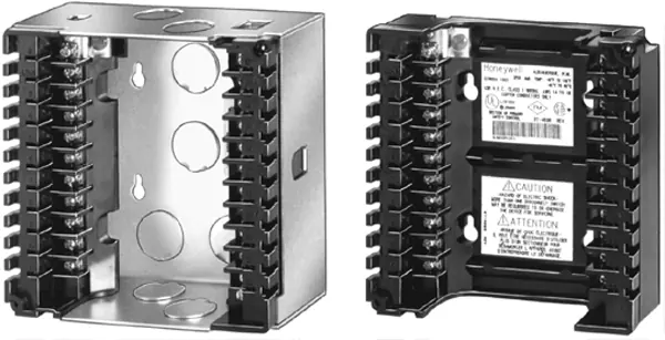
- 1000 Series Relay Modules: Use Q7800A1005/U (plastic) or Q7800B1003/U (metal) subbases.
- 2000 Series Relay Modules: Use Q7800A2005/U (plastic) or Q7800B2003/U (metal) subbases. These models feature a mandatory Grounding Pin in the corner. If this pin is missing or damaged, the 2000 Series module will not operate and warranties will be voided.
Installation
Installation must be performed by a trained, experienced Flame Safeguard service technician. Before beginning, disconnect all power supplies to prevent electrical shock and equipment damage.
Mounting Procedures
- Select a location within the ambient temperature rating of the Relay Module and S7830A.
- The subbase can be mounted on a wall, burner, or electrical panel.
- Warning: Do not mount the subbase horizontally with the bifurcated contacts pointing down. The standard vertical position is recommended.
- Ensure adequate clearance is provided for servicing, installation, and removal of the Relay Module, Keyboard Display Module, and flame amplifier signal probes.
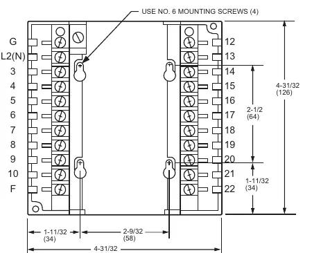
- For surface mounting, use the back of the subbase as a template to mark the four screw locations and drill pilot holes. Secure using four no. 6 screws.
Wiring
All wiring must comply with applicable local electrical codes, ordinances, and regulations. Use NEC Class 1 (Line Voltage) wiring.
- Wire Specifications: Use up to two no. 14, 16, or 18 copper conductors (TTW60C, THW75C, or THHN90C, 600V insulation).
- Grounding: Each Relay Module or S7830A has an earth ground terminal (G) that must be grounded to the metal control panel with the shortest practical wire.
- Separation: Do not run high voltage ignition transformer wires in the same conduit as flame detector wiring. Do not route scanner wires in the same conduit as line voltage circuits.
- Terminal Connections: Ensure no wiring projects beyond the terminal blocks. Tuck wiring against the back of the subbase to avoid interference with knife blade terminals.
Checkout
After installation, perform a complete system checkout. Voltage checks can be performed using the electrical access slots on the sides of the Q7800A/B. Always replace the electrical access slot covers on the Q7800B after performing checks to prevent electrical shock.
Manufacturer information
Honeywell International Inc.
Practical help
Common problems
2000 Series Relay Module fails to operate
Verify that the Grounding Pin is present and undamaged in the corner of the subbase.
Wiring interference with terminals
Ensure no wiring projects beyond the terminal blocks; tuck wiring against the back of the subbase.
High voltage interference
Do not run high voltage ignition transformer wires in the same conduit as flame detector wiring.
Before use
- Verify compatibility between the Relay Module (1000 vs 2000 series) and the Subbase.
- Ensure the power supply is disconnected before starting installation.
- Confirm the mounting location is within the ambient temperature rating.
- Ensure all wiring complies with NEC Class 1 (Line Voltage) standards.
- Check that the Grounding Pin is installed for 2000 Series modules.
Show more Show less
Specs in practice
- Terminal Screw Torque
- 12 lb-in typical, 13 lb-in maximum.
Images and diagrams
- Fig 1-4: Top and front views showing terminal layout, mounting holes, and conduit knockouts.
- Fig 2: Illustrates the location of the Grounding Pin required for 2000 Series modules.
Model compatibility
- 1000 Series Relay Modules are compatible with Q7800A1005/Q7800B1003.
- 2000 Series Relay Modules require Q7800A2005/Q7800B2003 and the Grounding Pin.

Manual page author
Michael Turner
Technical manual editor