Industrial / Gas Detection
Safety Manual for Honeywell Searchline Excel Plus & Edge
Comprehensive safety manual for the Honeywell Searchline Excel Plus & Edge open path flammable gas detector. Includes safety parameters, proof testing procedures, relay wiring configurations, and environmental specifications.
Table of contents
Important Safety Information
The Searchline Excel Plus & Edge is an open path flammable gas detector designed to alert users to potentially dangerous gaseous leaks. This manual provides critical safety parameters, proof testing procedures, and installation requirements for maintaining the safety integrity of the device.
Safety Function
The device provides two outputs for safety functions, compatible with different safety integrity levels:
- mA Output: Compatible with SIL 2 requirements. Values of 1.5 mA or below indicate a fault condition. Values above 4 mA up to 22 mA can be configured for leak levels or fixed alarms.
- Relay Output: Compatible with SIL 1 requirements. Includes independent Fault, Suspected Alarm, and Confirmed Alarm contacts.
Safety Parameters
The device is defined as a Type B device per IEC 61508 with an HFT of 0. Key safety parameters include:
- PFDavg (Relay Output SIL 1): 1.74E-03 (at 1-year interval)
- PFDavg (mA Output SIL 2): 5.61E-04 (at 1-year interval)
- Diagnostic Test Interval: Less than 30 seconds during normal operation.
Proof Test Interval
The nominal proof test interval is 12 calendar months. Users may vary this interval based on local conditions and system needs, provided the calculation method defined in IEC 61508 is used to maintain the required SIL level. Proof test variations should be reviewed annually.
Special Notes & Relay Wiring
When using relay outputs for safety purposes, adhere to the following:
- Relay contacts must be protected with a fuse rated at a maximum of 3 A.
- Only resistive loads should be connected to relay contacts.
- The fault relay output must be energised under normal conditions.
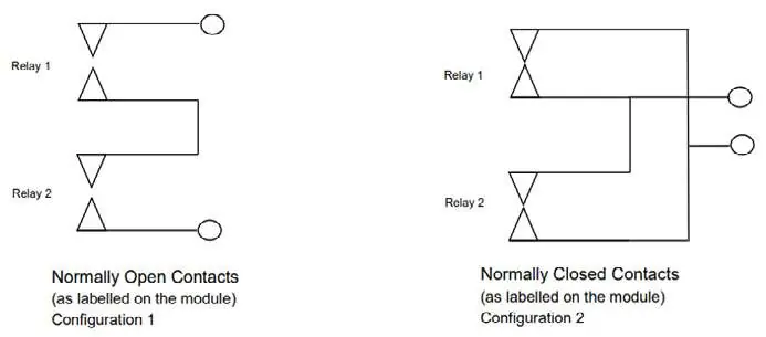
- For SIL 2 alarm configurations, wiring must follow specific configurations (Configuration 1 for open contact activation, Configuration 2 for closed contact activation).
Security: Access to the product via HART or Bluetooth requires authentication. Passwords and tokens should be managed to prevent unauthorised access.
Environmental Conditions
The device is designed to operate within the following parameters:
- Voltage: 18 to 32V DC
- Temperature: -55°C to +75°C
- Humidity: 0-100% RH Condensing
- Altitude: 0-1500m
- IP-Protection: IP 66/67 (Type 4X)
Proof Testing Procedures
Routine maintenance should be performed before specific proof tests:
- Visual Inspection: Check for loose connections, damage, corrosion, or contamination. Clean and repair as necessary.
- Electrical Testing: Test external cables for insulation resistance, shielding, earthing resistance, and cable continuity.
- Output Testing: Force relays to both de-energised and energised states. Test the mA loop at 4 mA and mid-range points.
- Bump Testing: Carry out in accordance with manufacturer technical specifications.
Manufacturer information
Honeywell International Inc.
Practical help
Common problems
Relay output fault
Ensure the fault relay is energised under normal conditions and that relay contacts are protected with a 3A fuse.
Unauthorised access
Change authentication passwords and tokens for HART or Bluetooth connections immediately if security is compromised.
Before use
- Verify firmware version is compatible with safety standards.
- Ensure power supply is of an isolating type (galvanic isolation).
- Confirm relay contacts are protected with a 3A fuse.
- Verify that only resistive loads are connected to relay contacts.
- Check environmental conditions (18-32V DC, -55°C to +75°C).
Images and diagrams
- Configuration 1: Wiring for Normally Open Contacts where an open contact represents safety function activation.
- Configuration 2: Wiring for Normally Closed Contacts where a closed contact represents safety function activation.
Model compatibility
- Compatible with SIL 1 and SIL 2 safety integrity levels.
- Requires isolating power supply (galvanic isolation from mains).
- Not compatible with non-resistive loads on relay contacts.

Manual page author
David Miller
Documentation analyst
Organizes user manual content into clear summaries, with attention to model details, product context, and everyday usability.