HVAC / Parts & Accessories
Honeywell 220738A Adapter Bracket Installation Guide
Official installation guide for the Honeywell 220738A Adapter Bracket. Includes mounting procedures for Modutrol IV motors, damper and valve linkage configurations, safety precautions, and system checkout steps.
Quick answers from the manual
Quick answer
- The 220738A Adapter Bracket raises the shaft height of Modutrol IV motors by 0.75 inches to match older Honeywell Modutrol motors in valve and damper linkage applications. p. 1
Key actions
- Mount the bracket to the equipment or linkage, then mount the motor to the bracket using the provided bolts. p. 1, 2, 3
Problems and fixes
Motor damage
Do not turn the motor shaft by hand or with a wrench.
p. 1, 2Show 2 more answers Show less
Technical specifications
| Parameter | Value | Meaning | Pages |
|---|---|---|---|
| Shaft height adjustment | 0.75 inch | Height increase provided by the bracket. | p. 1 |
Where to find it in the PDF
- Installation Instructions p. 1
- Damper Application Diagram p. 2
- Valve Linkage Application Diagram p. 3
Table of contents
Manual images
Click an image to enlargeQuick guide from the manual
The 220738A Adapter Bracket is designed to raise the shaft height of Modutrol IV motors by 0.75 inches. This adjustment is necessary to match the shaft height of older Honeywell Modutrol motors (such as M934, M975, M944, M945 types) in specific valve and damper linkage applications.
Installation
Before beginning, ensure the installer is a trained, experienced service technician. Always disconnect the power supply to prevent electrical shock and equipment damage.
Damper Linkage Applications
For damper applications, the bracket is optional for many setups. However, if the crank arm must rotate through the bottom plane of the actuator, the bracket or a shorter crank arm must be used.
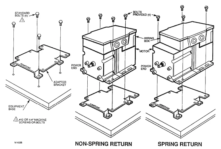
- Mount the bracket to the equipment using existing or standard bolts.
- Mount the motor to the bracket using the provided bolts.
- Note the specific configuration differences between spring return and non-spring return motors as shown in the installation diagrams.
Valve Linkage Applications
The adapter bracket is required for 0100, 0601, and 0618 linkages in all valve applications.
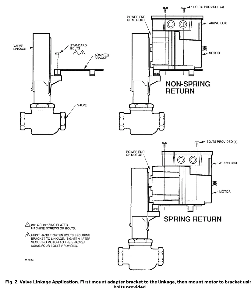
- Mount the bracket to the valve linkage first.
- Hand-tighten screws until the motor is secured to the bracket.
- Align the motor shaft to the valve linkage.
- Attach the motor to the bracket using the four provided bolts.
Safety and Operation
Caution: Never turn the motor shaft by hand or with a wrench, as this will damage the motor. Ensure the motor is mounted in a location free from acid fumes, explosive vapors, or gases. The shaft must remain horizontal.
Checkout
After installation, perform a thorough checkout:
- Adjust linkages so the damper or valve moves only through the maximum required distance.
- For modulating control, ensure the maximum damper opening is no more than 60°.
- Ensure the motor is stopped at the end of its stroke by the limit switch and is not stalled by the damper or valve.
Manufacturer information
Honeywell International Inc.
Practical help
Common problems
Motor shaft turned by hand or wrench
Do not turn the motor shaft manually; this will damage the motor.
Motor stalled by damper or valve
Ensure the motor is stopped at the end of its stroke by the limit switch and not by the damper or valve.
Improper damper opening
For modulating control, ensure the maximum damper opening is no more than 60°.
Before use
- Disconnect power supply before beginning installation.
- Verify the motor is a Modutrol IV model.
- Ensure the mounting location is free from acid fumes or explosive vapors.
- Verify the shaft remains horizontal.
- Ensure the installer is a trained, experienced service technician.
Show more Show less
Specs in practice
- Shaft height increase
- The bracket raises the motor shaft by 0.75 inches.
Images and diagrams
- Fig 1 illustrates the damper application mounting sequence.
- Fig 2 illustrates the valve linkage application mounting sequence.
Model compatibility
- Compatible with all Modutrol IV motors.
- Required for 0100, 0601, 0618 linkages in valve applications.
- Used to match older Honeywell Modutrol motors (e.g., M934, M975, M944, M945).

Manual page author
Michael Turner
Technical manual editor