Electronics / Monitors
Maintenance and Service Guide for HP 24fw and 27fw with Audio
A comprehensive maintenance and service guide for HP 24fw and 27fw with Audio monitors. This manual provides detailed instructions for professional service technicians, including safety precautions, component identification, disassembly...
Table of contents
Manual images
Click an image to enlargeImportant Service Information
This guide is intended for professional service technicians only. Before performing any maintenance or service, ensure the monitor is disconnected from the power source to prevent component damage. Always follow electrostatic discharge (ESD) safety procedures when handling electrical components. Repair must be performed in a professional repair center.
Monitor Features
The HP 24fw and 27fw with Audio monitors feature:
- 24fw: 23.8-inch diagonal viewable screen area with 1920 x 1080 resolution.
- 27fw: 27-inch diagonal viewable screen area with 1920 x 1080 resolution.
- Anti-glare screen with LED backlight.
- HDMI and VGA video inputs.
- AMD FreeSync support.
- Four assignable function buttons.
Components Identification
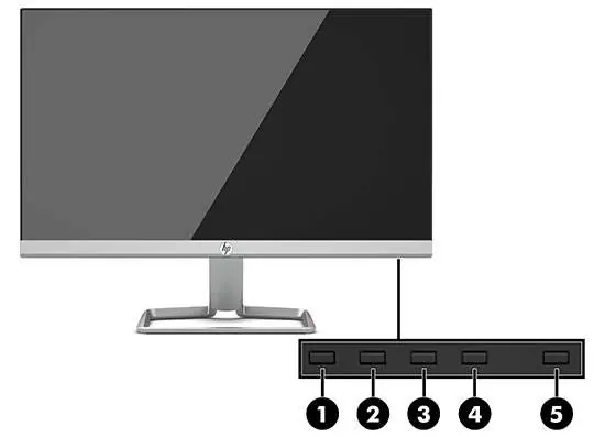
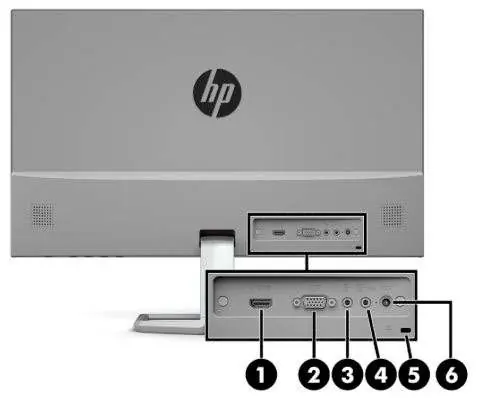
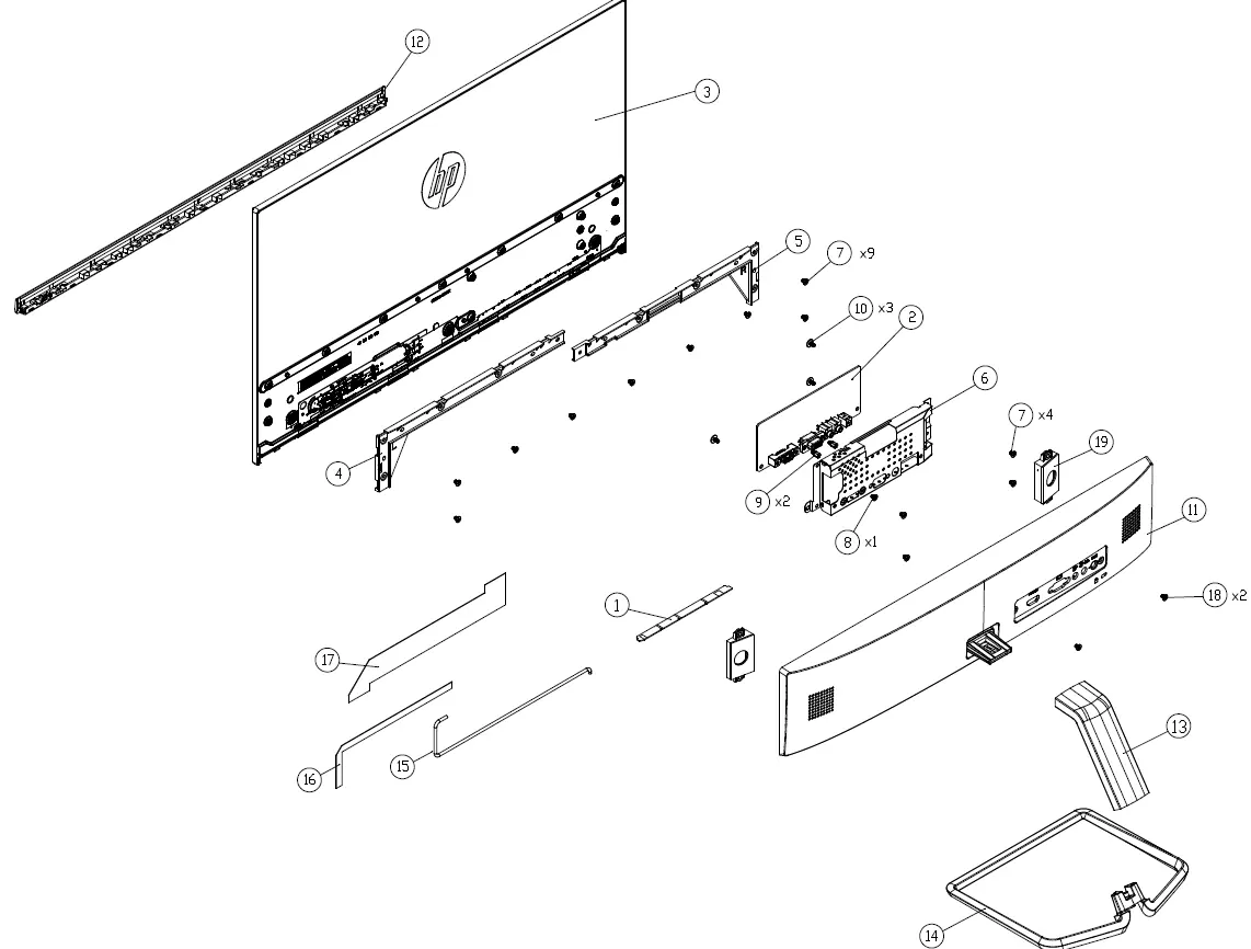
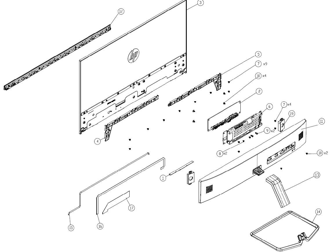
The monitor includes front-facing function buttons for OSD control and rear-facing ports for connectivity, including HDMI, VGA, Audio-in, and Audio-out jacks. Refer to the illustrated parts catalog for a detailed breakdown of internal components, including the display board, main board, and various frame/cover assemblies.
Disassembly Procedures
To disassemble the monitor, follow these general steps:
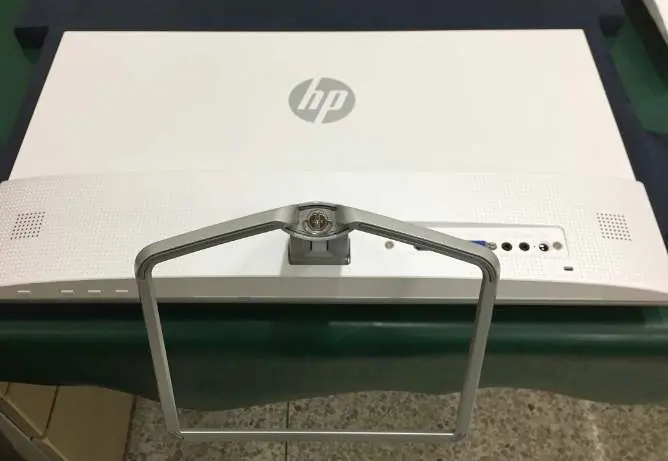
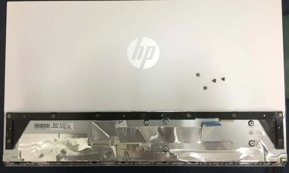
- Preparation: Ensure the workspace is clean, dry, and ESD-safe.
- Base Removal: Press the white button on the stand to release the base and stand assembly.
- Rear Cover: Remove the screws from the rear cover and carefully dismantle it.
- Shielding: Remove the rear cover supporter, disconnect LVDS/LED FFCs, and remove the screws securing the shielding to the main board.
- Internal Components: Release all materials and handle internal boards with ESD precautions.
Connector Repair
The guide provides specific procedures for repairing VGA (P100) and HDMI (P200/P201) connectors on the main board. This involves using a hot air gun to melt solder, removing the damaged connector, and soldering the new component to the PCB footprint.
Troubleshooting
Common issues such as a blank screen, blurred images, or locked OSD menus can often be resolved by checking cable connections, adjusting OSD settings, or performing a power cycle. If the power button is unresponsive, press and hold it for 10 seconds to disable the lockout feature.
Manufacturer information
HP Inc.
Practical help
Common problems
Screen is blank or video is flashing
Check if the power cord is connected, the monitor is powered on, the video cable is properly connected, or if the system is in Sleep mode.
Image appears blurred or too dark
Open the OSD menu and adjust the Brightness setting.
On-Screen Menus are Locked
Press and hold the Menu button on the front bezel for 10 seconds to disable the OSD lock function.
No low-power sleep mode
Press and hold the power button for 10 seconds to disable the power button lock function.
Before use
- Ensure the working environment is dry and clean.
- Use proper ESD protection when handling internal components.
- Disconnect the power cord from the power source before opening the monitor.
- Use approved tools and test equipment.
- Verify that replacement parts match the BOM and location specifications.
Show more Show less
Images and diagrams
- Exploded view of monitor components for 24fw and 27fw models.
- Front components diagram showing function buttons 1-5.
- Rear components diagram showing HDMI, VGA, and Audio ports.
- Connector repair diagrams for VGA and HDMI ports.
Model compatibility
- Firmware updates are available at support.hp.com.
- Connectors may need modification to meet specific regulatory or safety requirements if not an exact match.
- Use lead-free solder wire when soldering.

Manual page author
Michael Turner
Technical manual editor