Computers / Laptops
Maintenance and Service Guide for HP OMEN 24 Monitor
Comprehensive maintenance and service guide for the HP OMEN 24 gaming monitor. Includes disassembly procedures, parts catalog, connector repair instructions, and troubleshooting steps for professional technicians.
Table of contents
Manual images
Click an image to enlargeQuick guide from the manual
This document is a professional service manual intended for trained service personnel. It covers safety precautions, disassembly, parts replacement, and troubleshooting. Important: Always disconnect the power cord from the power source before opening the monitor to prevent component damage. Repair must be performed by professional service technicians in a repair center.
Monitor features
The HP OMEN 24 monitor features a 23.8-inch screen with 1920 x 1080 resolution at 165 Hz. It utilizes IPS or VA panel technology (depending on the model) with a nonglare LED backlight. Key features include tilt, swivel, and height adjustment, pivot capability, and OSD adjustments.
Rear components
The rear of the monitor contains the following controls and ports:
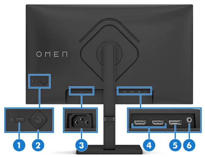
- Power button: Turns the monitor on or off.
- OSD control: Adjusts settings in the OSD menu.
- Power connector: Connects the power cord.
- HDMI ports (2): Video input for source devices.
- DisplayPort connector: Video input for source devices.
- Audio-out (headphone) jack: Connects headphones or speakers.
Illustrated parts catalog
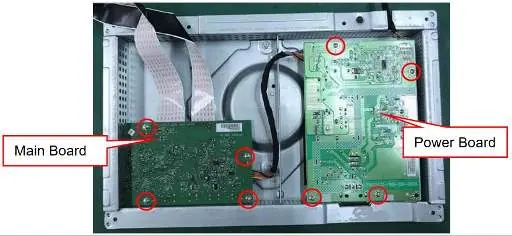
The monitor consists of several major components, including the panel, power board, main board, and various mechanical parts like the rear cover, hinge assembly, and stand. Refer to the parts catalog section for a complete list of items, including specific screw types (M3, D3, Q2) and board identifiers.
Removal and replacement procedures
Before disassembly, ensure the working environment is clean and ESD protection is used. Disassembly steps:
- Remove 4 screws from the hinge.
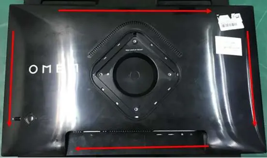
- Use fingers to split the left and right sides apart between the middle frame and rear case.
- Insert a scraper bar tool into the gap between the middle frame and rear case, then rotate to open the hooks.
- Disassemble the rear cover and disconnect the connector.
- Disassemble the key board and connector board if necessary.
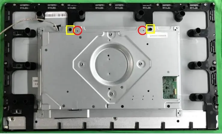
- Release screws and disconnect the FFC cable to separate the main frame from the panel.
- Remove the mylar, tear off tapes, and disassemble the boards from the housing.
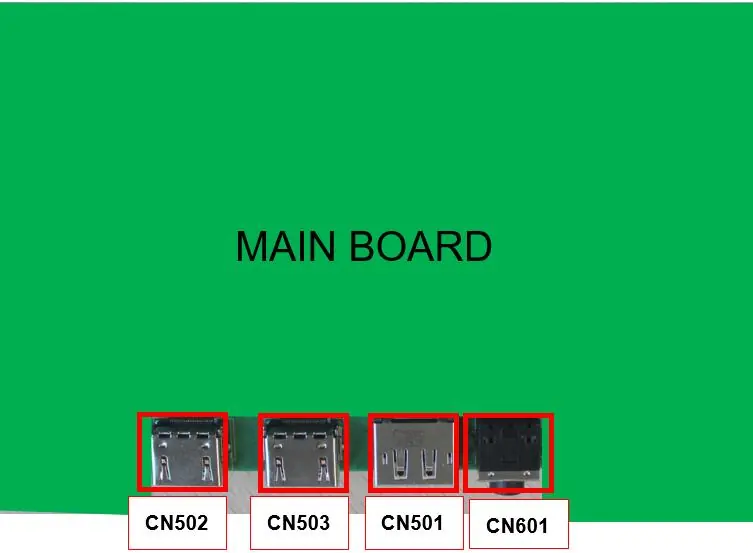
Connector repair
Connector repair (HDMI, DisplayPort, Phone Jack) is only for out-of-warranty units and must be performed by professional repairers. Use lead-free solder and work quickly to avoid overheating the circuit board. After repair, perform a close inspection and a function test to confirm the main board is operating correctly.

Function test
After any repair, confirm all functions are working. Perform an HDMI test, DP test, and Audio test using a computer or DVD player and speakers to ensure proper image display and sound output.
Support and troubleshooting
If the screen is blank or video is flashing, check the power cord, press the power button, or check the video cable connection. If the monitor does not enter sleep mode, check the OSD power settings. For OSD or Power Button Lockout, press and hold the respective button for 10 seconds to disable the lockout feature.
Manufacturer information
HP Inc.
Practical help
Common problems
Screen is blank or video is flashing
Check power cord, press power button, ensure video cable is connected properly, or disable Auto-Sleep mode.
Image appears blurred or too dark
Open the OSD menu and adjust the brightness setting.
Check Video Cable message displayed
Connect the appropriate video signal cable between the computer and monitor.
OSD Lockout or Power Button Lockout
Press and hold the Left button (for OSD) or Power button (for Power) for 10 seconds to unlock.
Before use
- Ensure the working environment is dry and clean.
- Disconnect the power cord before opening the monitor.
- Use ESD protection when handling internal components.
- Use lead-free solder for any soldering repairs.
- Verify capacitor polarity and specifications before replacement.
- Perform an AC leakage current check before returning the product.
Specs in practice
- Panel Technology
- IPS or VA (select models)
Images and diagrams
- Rear components diagram identifies the power button, OSD control, power connector, HDMI ports, DisplayPort, and audio jack.
- Parts catalog diagram shows the exploded view of the monitor, including the panel, boards, and housing components.
Model compatibility
- Connector repair is only for out-of-warranty units.
- Repair must be performed by professional service technicians.
- Firmware updates are available at support.hp.com.

Manual page author
David Miller
Documentation analyst
Organizes user manual content into clear summaries, with attention to model details, product context, and everyday usability.