Industrial / Temperature Controllers
User Manual for Icstation DC 12V Programmable Temperature Controller
Quick guide for the Icstation DC 12V Programmable Temperature Controller. Learn how to wire, configure temperature settings, adjust parameters (P0-P8), and troubleshoot display codes.
Table of contents
Manual images
Click an image to enlargeQuick Guide
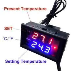
The Icstation DC 12V Programmable Temperature Controller is a digital thermostat designed for DIY temperature control systems. It features a 3-digit LED display, a waterproof NTC temperature sensor, and a 12V relay for controlling power to connected loads.
Specifications
- Measuring Range: -50°C to 110°C (-58°F to 230°F)
- Measuring Accuracy: ±0.1°C
- Controlling Accuracy: 0.1°C
- Power Supply: DC 12V 200mA
- Compatible Load: 5A/15A 220VAC, 20A 14VDC
- Sensor Type: 10K 0.5% NTC
- Working Temperature: -10°C to 60°C (14°F to 140°F)
Installation and Wiring
The device requires a 12V DC power supply. There are two primary wiring configurations depending on your setup:
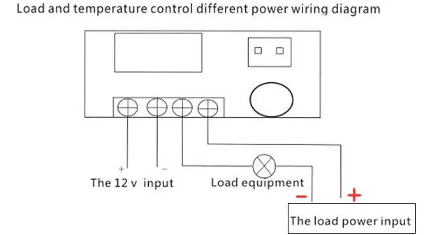
- Shared Power Supply: The controller and the load equipment share the same 12V power source.
- Separate Power Supply: The controller is powered by 12V, while the load equipment uses its own independent power source.
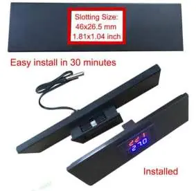
Ensure the sensor probe is connected securely. The module requires a slotting size of 46 x 26.5 mm (1.81 x 1.04 inch) for panel mounting.
Temperature Setting
- Press the SET button; the LED will flash.
- Use the SET(+) and C/F(-) buttons to adjust the desired temperature.
- Wait for 3 seconds; the module will automatically save the parameter and exit.
Parameter Settings
To access advanced settings (P0-P8), press and hold the SET button for 5 seconds. Use SET(+) or C/F(-) to navigate between codes. Press SET and C/F simultaneously to enter a specific parameter.
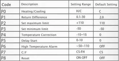
- P0 (Heating/Cooling): Select H (Heating) or C (Cooling). Default is C.
- P1 (Return Difference): Set the hysteresis (0.1-30). Default is 2.0.
- P2 (Set maximum limit): Default is 110.
- P3 (Set minimum limit): Default is -50.
- P4 (Temperature Correction): Range -15 to 15. Default is 0.
- P5 (Delay Start): Range 0-10. Default is 0.
- P6 (High Temperature Alarm): Range -50 to 110. Default is OFF.
- P7 (C/F): Switch between Celsius and Fahrenheit. Default is CS.
- P8 (Reset): Reset to factory settings. Default is OFF.
Display Codes and Troubleshooting
- LL: Sensor is in open circuit status. Check the sensor connection.
- HH: Temperature exceeds the module measuring range.
- --: The module is in high temperature protection status.
Practical help
Common problems
Display shows 'LL'
The sensor is in open circuit status. Check the connection of the NTC probe.
Display shows 'HH'
The temperature exceeds the module's measuring range (-50°C to 110°C).
Display shows '--'
The module is in high temperature protection status.
Before use
- Verify the power supply is 12V DC.
- Ensure the load equipment does not exceed 5A/15A 220VAC or 20A 14VDC.
- Check that the NTC sensor probe is properly connected.
- Determine if you need a shared or separate power supply wiring configuration.
- Ensure the mounting slot is 46 x 26.5 mm.
Specs in practice
- Return Difference (P1)
- The hysteresis value; the difference between the temperature at which the relay turns on and off.
- Refresh Frequency
- The rate at which the display updates (0.5 seconds).
- Compatible Load
- The maximum electrical capacity the relay can switch (5A/15A 220VAC or 20A 14VDC).
Images and diagrams
- Wiring Diagram 1: Shows how to connect the controller and load when sharing the same 12V power supply.
- Wiring Diagram 2: Shows how to connect the controller and load when using separate power supplies for each.
Model compatibility
- Requires 12V DC power supply.
- Compatible with 10K 0.5% NTC sensors.
- Not suitable for loads exceeding 20A at 14VDC or 15A at 220VAC.

Manual page author
Michael Turner
Technical manual editor
Reviews PDF manuals for structure, safety notes, and practical product details so readers can find the right information quickly.