Industrial / Temperature Controllers
Icstation 108.0MHz Wireless FM Radio Receiver DIY Kit
Quick guide for the Icstation 108.0MHz Wireless FM Radio Receiver DIY Kit. Includes assembly instructions, component list, operating methods, and technical specifications.
Table of contents
Manual images
Click an image to enlargeQuick guide from the manual
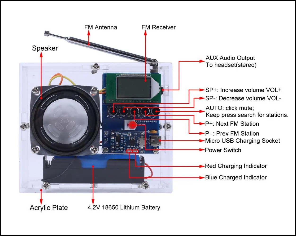
The Icstation 108.0MHz Wireless FM Radio Receiver is a DIY kit designed for training welding skills and electronic project design. It features an HD LCD display, automatic station search, and a built-in 5W power amplifier. The device supports a frequency range of 76.0MHz-108.0MHz and includes a power-saving mode.
Operating instructions
Basic Controls:
- Power Switch: Turns the device ON/OFF.
- AUTO Button: Long press to automatically search and store FM stations. Short press to toggle the mute function.
- P+/P- Buttons: Switch between saved FM stations.
- SP+/SP- Buttons: Adjust volume from V00 to V30.
Advanced Settings:
- Campus Broadcasting Band: Keep SP+ and SP- pressed before powering on. Display C1 enables the band; C0 disables it.
- Backlight Mode: Keep P+ and P- pressed before powering on. Display B1 keeps the backlight ON; B0 turns it off after 20 seconds (power saving mode).
Charging: The device uses a red LED indicator for charging and a blue LED for fully charged. Note that the FM radio cannot be played while charging.
Assembly and installation
Installation Tips:
- Prepare necessary tools: Soldering iron (<50W), rosin core solder, wire cutters, wire strippers, and a screwdriver.
- Do not touch components with the soldering iron for more than 1 second to avoid damage.
- Pay attention to component polarity and installation direction.
- Wear anti-static protection during assembly.
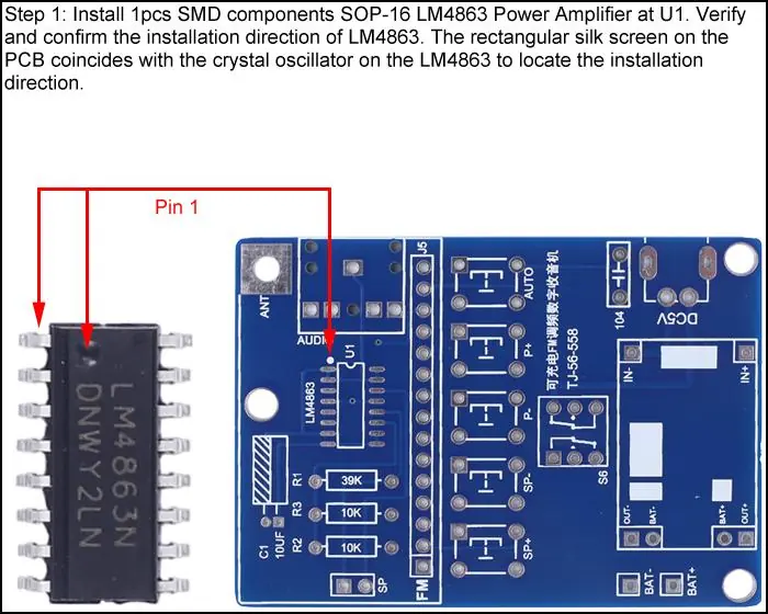
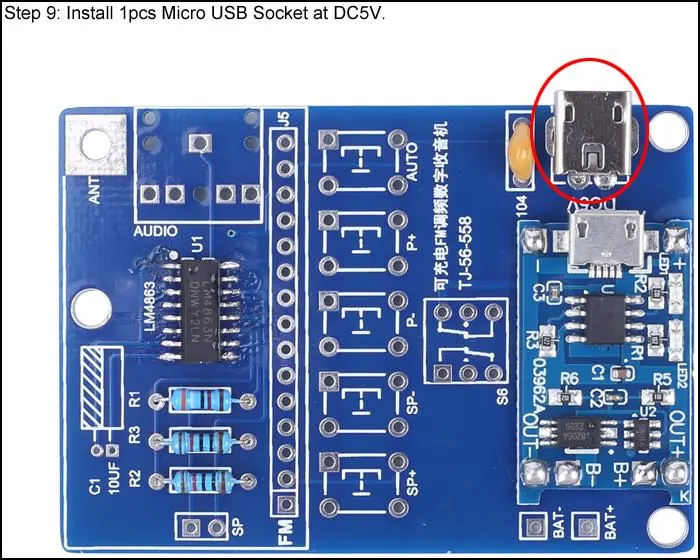
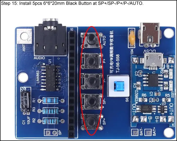
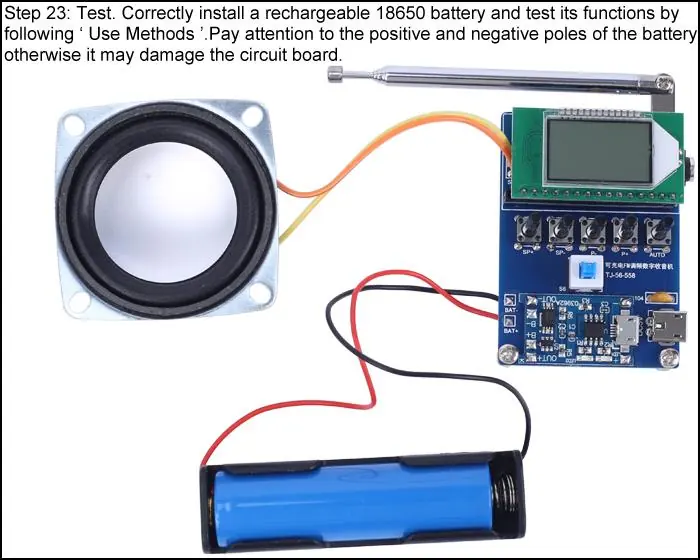
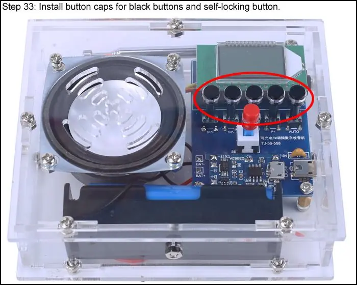
Assembly Steps: The assembly involves soldering SMD components (LM4863), resistors, capacitors, and sockets onto the PCB, followed by connecting the speaker and antenna. Finally, the acrylic shell is assembled around the PCB using copper pillars and screws.
Component list
The kit includes essential parts such as the LM4863 Power Amplifier, FM Receiver Module, 18650 Lithium Battery, 5W Speaker, various resistors, capacitors, buttons, and an acrylic housing set. Users should verify all components against the provided list before starting assembly.
Schematic diagram
The manual provides a detailed schematic diagram illustrating the electrical connections between the FM receiver module, the power amplifier, the charging circuit, and the control buttons.
Practical help
Common problems
FM radio cannot be played
Ensure the device is not currently charging, as radio playback is disabled during charging.
Speaker does not work
Check if earphones are connected to the AUX jack; the speaker is automatically disabled when earphones are plugged in.
LEDs do not light up
Verify that LEDs were installed according to the specified polarity rules.
Before use
- Soldering iron (<50 Watt)
- Rosin core solder
- Wire cutters
- Wire strippers
- Anti-static gloves or wristbands
Specs in practice
- Work Voltage
- DC 3.0V-5.0V
- Output Power
- 5W
- Frequency Range
- 76.0MHz-108.0MHz
- Output Impedance
- 8ohm
Images and diagrams
- The schematic diagram illustrates the integration of the FM receiver module, the LM4863 amplifier, and the battery charging circuit.
Model compatibility
- Requires an 18650 Lithium Battery (not included in the kit).

Manual page author
Emily Carter
User documentation editor
Prepares concise manual descriptions and highlights the most useful setup, operation, and maintenance information for readers.