Industrial / Temperature Controllers
User Manual for AKO 1301H201 Temperature Controller
Quick guide for the AKO 1301H201 temperature controller. Includes installation instructions, wiring diagrams, parameter configuration, and troubleshooting steps for thermometers and thermostats.
Table of contents
Manual images
Click an image to enlargeQuick guide from the manual
The AKO 1301H201 is a small-dimension unit designed for monitoring, controlling, and regulating refrigerating or heating generators. This document covers installation, configuration, and maintenance. Note that programming should only be performed by qualified personnel. The device features password protection for settings and supports parameter transfer between units.
Installation
The controller must be installed in a location protected from vibrations, water, and corrosive gases. The ambient temperature must be between 5°C and 40°C.
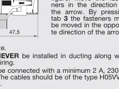
- Fastening: Place the fasteners over the sliders on the unit. Move the fasteners in the direction of the arrow to secure the unit. To remove, press tab 3 and move in the opposite direction.
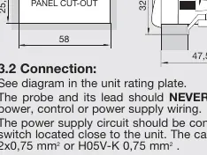
- Gasket: To ensure IP65 protection, install the gasket properly between the apparatus and the perimeter of the panel cut-out.
- Wiring: The probe and its lead must never be installed in ducting along with power or control wiring. Use a minimum 2A, 230V switch located close to the unit.
Front Panel Functions
- UP key: In programming, increases the displayed value. Press for 5 seconds to start a manual defrost (in thermostat function).
- DOWN key: In programming, reduces the displayed value.
- SET key: Press for 5 seconds to display the SET POINT temperature. In programming, accepts the new value.
- LED 1: Defrost in operation indicator.
- LED 2: Relay ON indicator. Flashing indicates the programming phase.
Adjustment and Configuration
Set Point Temperature:
- Press the SET key for at least 5 seconds to display the current SET POINT. LED 2 will flash.
- Use the UP or DOWN keys to change the value.
- Press the SET key to accept the new value.
Parameters Configuration:
- Level 1: Press UP and DOWN keys simultaneously for at least 10 seconds. LED 2 will flash, and the first parameter (C0) will appear.
- Navigation: Use the SET key to access the next parameter and the UP/DOWN keys to change values.
- Exit: Pressing the SET key at the last parameter (EP) returns the controller to the current temperature display.
Parameters Transfer
Using the AKO-14918 portable server, parameters can be copied from a powered unit and transferred to other identical units without needing a power supply for the server.
Relay Operation
The relay operation depends on the P0 parameter:
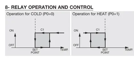
- Cold (P0=0): Relay activates to cool.
- Heat (P0=1): Relay activates to heat.
Maintenance and Troubleshooting
Clean the surface with a soft cloth, soap, and water. Do not use abrasive detergents, petrol, alcohol, or solvents.
Common Messages:
- dF: Defrosting in progress (if parameter d2 is set to 2).
- E1: Sensor failure (Open circuit, crossed, temp > 110°C or < -55°C).
- --: Temperature > 99°F.
- EE: Memory failure.
- PA: Password request.
Manufacturer information
AKO Group
Practical help
Common problems
E1 error code
Sensor failure detected. Check for open circuit, crossed wires, or if temperature is outside the range of -55°C to 110°C.
EE error code
Memory failure. The unit may require service.
PA message
Password request. Enter the password programmed in parameter L5 to access settings.
Cannot change parameters
Ensure you are in the correct programming level (Level 1 or 2) and that the password (if set) has been entered correctly.
Before use
- Ensure the installation site is protected from vibrations, water, and corrosive gases.
- Verify the ambient temperature is within 5°C to 40°C.
- Install the gasket properly for IP65 protection.
- Ensure the probe is placed away from heat sources other than the target.
- Use a minimum 2A, 230V switch near the unit.
- Use only NTC probes supplied by AKO.
Specs in practice
- Temperature range
- -50°C to 99°C.
Images and diagrams
- Fastening: Shows how to slide fasteners over the unit and lock them into the panel cut-out.
- Relay Operation: Illustrates the difference between Cold (P0=0) and Heat (P0=1) modes.
- Parameters Transfer: Shows the connection between the AKO-14918 server and the controller.
Model compatibility
- Probe extension cable ref. AKO-15586 allows extension up to 1000m with minimal deviation.
- Only use NTC probes supplied by AKO.

Manual page author
David Miller
Documentation analyst
Organizes user manual content into clear summaries, with attention to model details, product context, and everyday usability.