Electronics / USB Extenders
User Manual for Infobit iTrans USB 2.0 Extender (100M)
Quick guide for the Infobit iTrans USB 2.0 Extender (100M). Learn how to connect your transmitter and receiver, understand the PoC power function, and troubleshoot signal transmission issues.
Table of contents
Manual images
Click an image to enlargeQuick guide from the manual
The Infobit iTrans USB 2.0 Extender allows you to extend USB signals up to 100 meters (328ft) using a standard Cat 5e/6 cable. The system features PoC (Power over Cable) technology, meaning you only need to connect the 12V/1A power adapter to either the transmitter or the receiver to power both units.
Product Overview
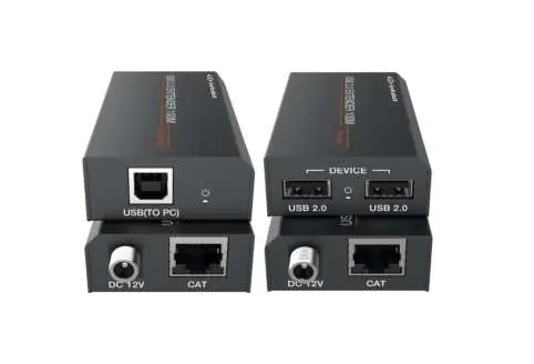
The system consists of two units: a Transmitter (connected to the PC) and a Receiver (connected to USB devices). It supports plug-and-play functionality, requiring no additional drivers or software installations.
Package Contents
- 1x USB 2.0 Extender (Transmitter)
- 1x USB 2.0 Extender (Receiver)
- 1x USB cable (USB-B to USB-A, 1 meter)
- 1x 12V/1A Locking Power Adapter
Specifications
- USB Protocol: USB 2.0
- Transmission Rate: Up to 480Mbps
- Transmission Distance: Up to 100 meters (328ft) via Cat 5e/6 cable
- Power Supply: Input AC100~240V 50/60Hz, Output DC 12V/1A
- ESD Protection: Human-body Model: ±8kV (Air-gap discharge), ±4kV (Contact discharge)
- Operating Temperature: 0°C to 40°C (32°F to 104°F)
Operation Controls
Transmitter (Front Panel)
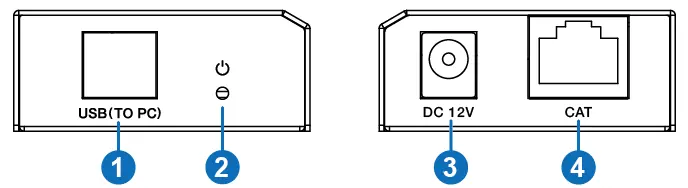
- USB Port: Connects to the PC using the provided USB-B to USB-A cable.
- Power LED: Illuminates green when the transmitter is powered.
- DC 12V: Power input port.
- CAT Port: Connects to the receiver via Cat 5e/6 cable.
Receiver (Rear Panel)
- USB 2.0 Ports: Two ports for connecting USB devices such as printers, U disks, or cameras.
- Power LED: Illuminates green when the receiver is powered.
- DC 12V: Power input port.
- CAT Port: Connects to the transmitter via Cat 5e/6 cable.
Connection Diagram
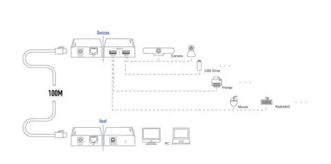
To set up the system, connect the Transmitter's USB port to your PC. Connect the Receiver's USB ports to your peripheral devices. Link the Transmitter and Receiver using a Cat 5e/6 cable. Connect the 12V power adapter to either the Transmitter or the Receiver to power the entire system.
Practical help
Common problems
Power LED does not illuminate
Ensure the 12V/1A power adapter is securely connected to an AC outlet and the unit.
No signal transmission
Verify the Cat 5e/6 cable is properly connected to the CAT ports on both units and is not damaged.
USB device not recognized
Ensure the USB-B cable is correctly connected between the PC and the Transmitter.
Before use
- Ensure you have a high-quality Cat 5e/6 cable for the connection.
- Verify the 12V/1A power adapter is available.
- Check that the PC is ready for USB connection.
- Confirm the distance between units does not exceed 100 meters.
Specs in practice
- Transmission distance
- Maximum range of 100 meters (328ft) using Cat 5e/6 cabling.
- PoC (Power over Cable)
- Allows powering both units using a single power adapter connected to either the transmitter or receiver.
Images and diagrams
- Transmitter connects to PC via USB-B.
- Receiver connects to USB devices (printer, U disk, etc.).
- Transmitter and Receiver are linked via Cat 5e/6 cable.
Model compatibility
- Requires Cat 5e/6 cable for operation.
- Supports USB 2.0 devices.

Manual page author
Michael Turner
Technical manual editor
Reviews PDF manuals for structure, safety notes, and practical product details so readers can find the right information quickly.