Electronics / Networking
User Manual for Intellinet 561761 v2 24-Port Gigabit Ethernet PoE+ Switch
Quick installation and operation guide for the Intellinet 561761 v2 24-Port Gigabit Ethernet PoE+ Switch. Includes rack mounting instructions, LED status explanations, and safety guidelines.
Quick answers from the manual
Quick answer
- The Intellinet 561761 v2 is a 24-port Gigabit Ethernet PoE+ switch with four 10G SFP+ ports. It supports rack mounting and features Auto-MDI/MDI-X ports for flexible cabling. p. 1, 2
Key actions
- Rack mounting the switch p. 2
- Connecting the switch p. 2
First start
- Power on and verify p. 2
Show 4 more answers Show less
Problems and fixes
LED status indicates no link or activity
Check the corresponding device for proper setup and operation.
p. 2Maintenance and reset
- Cleaning p. 8
Technical specifications
| Parameter | Value | Meaning | Pages |
|---|---|---|---|
| PoE Standard | IEEE 802.3af/at | Power over Ethernet compliance | p. 2 |
| Cable Compatibility | Cat5/5e/6 UTP/STP | Recommended cabling for optimal performance | p. 2 |
Where to find it in the PDF
- Installation and Placement p. 2
- Connections and LEDs p. 2
- Safety Instructions p. 8
Table of contents
Manual images
Click an image to enlargeQuick Guide
This guide provides the basic steps to set up and operate the Intellinet 561761 v2 24-Port Gigabit Ethernet PoE+ Switch. For detailed technical specifications, visit intellinetnetwork.com.
Placement
To ensure proper operation and longevity of the switch, follow these placement guidelines:
- Place the device on a level surface capable of supporting its weight.
- Maintain a minimum clearance of 25 mm (approx. 1 inch) on the top and sides for adequate ventilation.
- Keep the device away from sources of electrical noise, such as radios, transmitters, and broadband amplifiers.
- Avoid environments with excessive moisture.
Rack Mounting
The switch includes brackets and screws for optional rack mounting. Follow these steps:
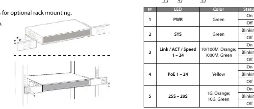
- Disconnect all cables from the switch.
- Position a bracket over the mounting holes on one side of the switch and secure it with the provided screws.
- Repeat the process for the other side of the switch.
- Position the switch in the rack and screw the brackets to the rack frame.
- Reconnect all cables.
Chassis Grounding
A grounding terminal is located on the side of the power supply connector. If using the chassis grounding screw, ensure it is wired to an object that provides a direct earth ground. In rackmount installations, this is typically provided by the metal frame of the mounting rack.
Connections
The switch features Auto-MDI/MDI-X ports, allowing the use of straight or crossover UTP/STP cables. Cat5/5e/6 cables are recommended for optimal performance. Connect the included power cable to the receptacle on the back of the switch and verify that the PWR LED lights up. All RJ45 ports provide power to connected devices; ensure all connected devices are compliant with IEEE 802.3af/at standards.
LED Indicators
Monitor the switch status using the front panel LEDs:
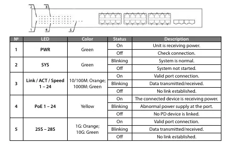
- PWR: Green. On = Unit is receiving power. Off = Check connection.
- SYS: Green. Blinking = System is normal. Off = System not started.
- Link / ACT / Speed (1-24): 10/100M (Orange), 1000M (Green). On = Valid connection. Blinking = Data transmission. Off = No link.
- PoE (1-24): Yellow. On = Device receiving power. Blinking = Abnormal power supply. Off = No PD device linked.
- 25S - 28S: 1G (Orange), 10G (Green). On = Valid connection. Blinking = Data transmission. Off = No link.
Safety Instructions
- Intended Use: For indoor, non-critical applications only.
- Electrical Safety: Use only the original or approved power adapter. Keep ports and cables clean and dry. Disconnect power before cleaning or servicing.
- Handling: Do not insert foreign objects into ports. If the product is dropped, punctured, or exposed to liquid, discontinue use and contact support.
- Repairs: Do not attempt to open or repair the product yourself; unauthorized repairs void the warranty.
Official resources from the manual
Manufacturer information
Intellinet Network Solutions
Practical help
Common problems
PWR LED is off
Check the power cable connection to the switch and the power outlet.
No link or activity LED
Check the connected device for proper setup, configuration, and power.
Abnormal PoE power supply (PoE LED blinking)
Verify that the connected device is compliant with IEEE 802.3af/at standards.
Before use
- Ensure the surface can support the switch's weight.
- Provide at least 25 mm of clearance for ventilation.
- Keep away from sources of electrical noise.
- Verify the power source is active.
- Use Cat5/5e/6 UTP/STP cables for optimal performance.
Show more Show less
Specs in practice
- Auto-MDI/MDI-X
- Allows the use of both straight and crossover cables for connections.
- IEEE 802.3af/at
- Standard for Power over Ethernet (PoE) compatibility.
- 10G SFP+ Ports
- High-speed uplink ports for fiber or copper SFP+ modules.
Images and diagrams
- Rack mounting bracket installation procedure.
- LED indicator status table for monitoring switch health and connections.
Model compatibility
- Supports IEEE 802.3af/at compliant devices.
- Compatible with Cat5, Cat5e, and Cat6 UTP/STP cables.

Manual page author
Michael Turner
Technical manual editor