Furniture / Storage Shelving
Assembly Instruction for Invicta Interior Paris Chesterfield Bed
Quick assembly guide for the Invicta Interior Paris Chesterfield bed. Includes step-by-step instructions, parts list, and hardware requirements for models 39992, 39993, 39994, 40556, and 40557.
Table of contents
Manual images
Click an image to enlargeQuick guide from the manual
This bed is delivered in two separate packages. Before beginning assembly, ensure you have both packages and all necessary hardware components. The assembly requires basic tools and should be performed on a clear, flat surface.
Parts List
- A: Corner bracket
- B: Corner bracket
- C: Wrench
- D: Screw (20H mm)
- E: Allen key
- F: Wooden legs and accessories
- G: Corner bracket
- H: Screw (25H mm)
- I: Middle wooden bar
- J: Middle wooden leg
- K: Corner bracket
Assembly Steps
Step 1: Preparation
Locate Package 1 and 2 containing the headboard, side frames, footboard, and all accessories.
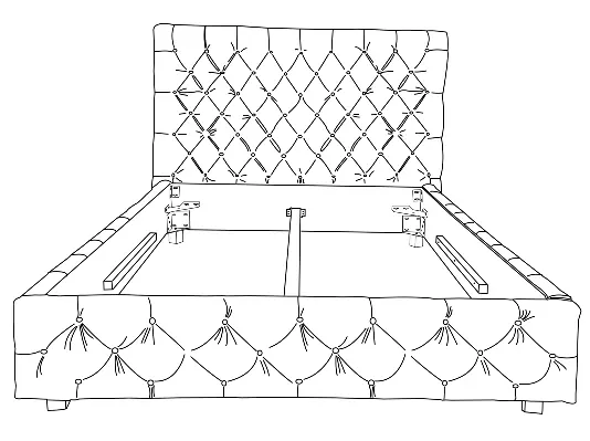
Step 2: Side Frames to Headboard
Connect the side frames to the headboard using the corner hardware (A+B). Secure each corner with a total of 10 screws (D).
Step 3: Footboard to Sideframes
Connect the footboard to the sideframes using the corner hardware (A+B+K). Secure each corner with a total of 14 screws (D).
Step 4: Legs
Attach the wooden legs (F) to the corner hardware (B).
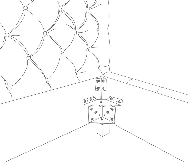
Step 5: Corner Fittings and Middle Support
Attach the corner fittings using 12 screws (G+H) to the headboard and footboard. Install the middle wooden bar (I) and the middle wooden leg (J).
Step 6: Final Assembly
Place the middle wooden bar (I+J) onto the corner hardware (G) to complete the structure.
Manufacturer information
Invicta Interior GmbH & Co. KG
Practical help
Common problems
Missing parts or hardware
Ensure you have received both Package 1 and Package 2. If parts are missing, contact your dealer directly.
Difficulty identifying screws
Refer to the parts list on page 1. Screws are categorized by length (20H mm, 25H mm, 35H mm). Ensure you use the correct length for each step.
Before use
- Verify you have received two packages.
- Clear a large space for assembly.
- Identify all hardware (A-K) listed on page 1.
- Ensure you have the provided wrench (C) and Allen key (E).
Specs in practice
- Screw D (20H mm)
- Primary screw used for corner hardware assembly.
- Screw H (25H mm)
- Used for securing corner fittings.
- Screw (35H mm)
- Used for specific leg/hardware attachments.
Images and diagrams
- The diagrams illustrate the correct orientation of corner brackets (A, B, K) and the placement of the middle support bar (I+J).
Model compatibility
- This manual applies to article numbers: 39992, 39993, 39994, 40556, 40557.

Manual page author
Emily Carter
User documentation editor
Prepares concise manual descriptions and highlights the most useful setup, operation, and maintenance information for readers.