Industrial / Communication Modules
User Manual for IXYS Dual Responder Trigger Ethernet
Quick guide for the IXYS Dual Responder Trigger Ethernet. Learn about configuration, wiring, web interface settings, and troubleshooting for this communication module.
Table of contents
Quick Guide
The IXYS Dual Responder Trigger Ethernet is a PCB module designed to read digital on/off signals at one location and forward them to another board via Ethernet UDP packets. It ensures low latency transmission, where the output pulse length matches the incoming signal. This manual is intended for trained and competent personnel only.
Health and Safety
Safety precautions must be followed to prevent electrical and mechanical hazards. Personnel must be appropriately qualified and trained in the operation and maintenance of this equipment. Failure to comply with safety guidelines may result in product damage, property damage, or serious injury.
Technical Data
- Manufacturer: Ixys AS
- Part Number: 118092
- Weight: 39g
- Dimensions: 96 x 90 x 15 mm
- Supply Voltage: 9 – 28 V DC
- Power Consumption: 36 mA @ 24 V DC
- Communication: Ethernet 10 / 100 Mbps (Auto negotiation and Auto MDIX enabled)
- Digital Input: 0 / 5 V DC
Drawing and Pin Configuration
The board features specific headers for connectivity:
- J1 / J2: Trigger I/O channels (Pin 2: Trigger OUT, Pin 3: Trigger IN, Pin 4: 0V).
- J3: Power supply input (Pin 2: 24VDC, Pin 3/4: 0V).
- J4: Ethernet port.
- JH1: Programming header.
Configuration
To configure the device, connect a computer to the same network as the PCB. If the IP is unknown, use the Wireshark network utility to look for heartbeat messages at a 1Hz interval to IP 255.255.255.255 on port 65000. Access the built-in web server by entering the PCB IP address in a web browser.
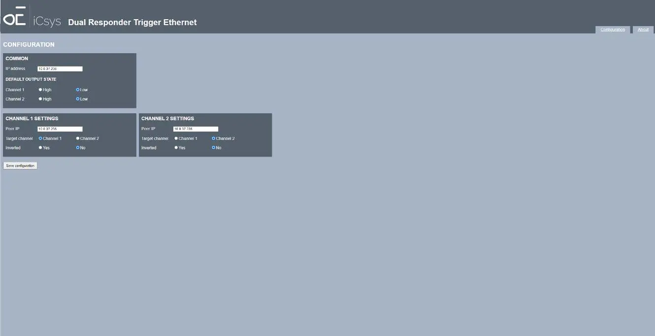
Configuration Page Settings:
- IP Address: The IP address of the PCB.
- Default Output State: High/low state of outputs at startup.
- Peer IP: The IP address of the destination PCB.
- Target Channel: The target channel on the destination PCB.
- Inverted: Option to invert the input signal before transmission.
Firmware Updates
The "About" page provides hardware and firmware version information and allows for firmware updates. Select the firmware file and press "Upload" to initiate the process.
Troubleshooting
If you encounter issues, check the following:
- No connection to PCB: Verify power supply, check ethernet wiring, and ensure the computer is in the same subnet as the PCB.
- LED on destination PCB does not blink: Check the Peer IP configuration and verify that the input signal voltage is within limits.
- Activity LED does not blink (orange): This may indicate a faulty board; return for repair.
Practical help
Common problems
No connection to PCB from computer
Check power supply, verify ethernet wiring, and ensure the computer IP is in the same subnet as the PCB.
LED on destination PCB does not blink
Check Peer IP configuration and verify that the input signal voltage is within the 0/5V DC range.
Activity LED does not blink (orange)
The board may be faulty; return for repair.
Before use
- Ensure personnel are trained and qualified.
- Verify power supply is between 9-28V DC.
- Connect the PCB to the network.
- If IP is unknown, use Wireshark to find the heartbeat message.
- Access the web interface via a browser.
Specs in practice
- Supply voltage
- 9-28V DC input required for operation.
- Communication
- Ethernet 10/100 Mbps with Auto negotiation and Auto MDIX.
- Digital input
- Accepts 0/5V DC signals.
Images and diagrams
- J1/J2: Trigger I/O channels for signal input/output.
- J3: Power supply input terminal.
- J4: Ethernet connection port.
- JH1: Programming header for firmware/debug.
Model compatibility
- Requires Ethernet network connection.
- Requires web browser for configuration.
- Requires Wireshark for initial network discovery if IP is unknown.

Manual page author
Emily Carter
User documentation editor
Prepares concise manual descriptions and highlights the most useful setup, operation, and maintenance information for readers.