Industrial / Communication Modules
User Manual for Assured Systems 104-COM232-8 Serial Communication Board
Quick guide for the Assured Systems 104-COM232-8 serial communication board. Includes installation steps, jumper configuration, Windows COM port setup, and technical specifications.
Table of contents
Manual images
Click an image to enlargeQuick guide from the manual
This manual provides instructions for the Assured Systems 104-COM232-8, 104-COM232-4, and 104-COM232-2 serial communication boards. These boards are designed in the PC/104 format and provide RS-232 communication. Warning: Always turn off computer power before installing or removing the board or connecting/disconnecting cables to avoid damage and voiding warranties.
Hardware Installation
Before installing the board, configure the jumpers for the desired base address and options. Ensure that the address ranges do not overlap with other functions in your system to prevent unpredictable behavior. The FINDBASE.EXE program provided on the CD can assist in selecting a base address.
- Remove power from the PC/104 stack.
- Assemble standoff hardware for stacking and securing the boards.
- Plug the board onto the PC/104 connector on the CPU or onto the stack, ensuring proper pin alignment.
- Install I/O cables onto the board's connectors.
- Check all connections before powering up the system.
- Run the provided sample programs from the CD to validate the installation.
Software Installation
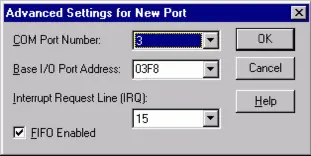
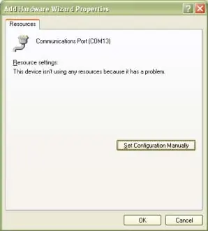
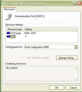
The software provided on the CD must be installed prior to use. Follow the on-screen prompts for your specific operating system (DOS, Windows, or Linux). For Windows XP and NT4, specific manual configuration of COM ports via the Control Panel or Registry may be required to set base addresses and IRQs.
Option Selection
The operation of the serial communications section is determined by jumper installation. Refer to the Option Selection Map in the manual to locate jumpers. The board supports interrupt levels 2, 3, 5, 7, 10, and 11. The same interrupt is used for all channels and must be entered into the interrupt location in the EEPROM.
Programming
Port addresses and IRQs are selected by software through a control block, with the base address selected by jumpers. The board includes an onboard EEPROM to store these settings. Data can be written to the EEPROM by writing the address to the EEPROM Address register, then writing to or reading from the EEPROM Data register. A 2ms wait is required between EEPROM operations.
Specifications
- Ports: 8, 4, or 2 (varies by version)
- Type: RS-232
- Bus: PC/104, ISA
- UART: 16C654 (8-port uses 16L788)
- Throughput: Up to 230.4 kbps
- Operating Temperature: 0 to +60 °C
- Power Required: +5 VDC at 400 mA typical (800 mA max for 8-channel)
Official resources from the manual
Practical help
Common problems
Unpredictable computer behavior
Check for address overlaps; ensure base addresses are unique and do not conflict with other system functions.
No communication
Verify the DLAB bit is set to zero after the divisor is loaded; ensure the correct baud rate divisor is used.
Hardware not detected
Ensure jumpers are correctly set and the board is seated properly in the PC/104 stack.
Before use
- Power off the computer before installing the board.
- Configure jumpers for base address and options before installation.
- Install software from the provided CD.
- Verify address ranges do not overlap with other system functions.
- Check all connections in the PC/104 stack before powering up.
Specs in practice
- Operating Temperature
- 0 to +60 °C
- Power Required
- +5 VDC at 400 mA typical, 800 mA maximum (8-channel card)
Images and diagrams
- Option Selection Map: Shows jumper locations on the board.
- Connector Pin Assignments: Details pinout for P2 and P3 connectors.
Model compatibility
- Compatible with PC/104 format.
- Supports Windows and DOS environments.

Manual page author
Michael Turner
Technical manual editor
Reviews PDF manuals for structure, safety notes, and practical product details so readers can find the right information quickly.