Industrial / Communication Modules
User Manual for Danfoss AK-CM 101A and AK-CM 101C Communications Module
Quick guide for Danfoss AK-CM 101A and AK-CM 101C communications modules. Includes mounting instructions, address configuration, power requirements, and data communication setup.
Table of contents
Manual images
Click an image to enlargeQuick guide from the manual
The Danfoss AK-CM 101A and AK-CM 101C are communications modules designed for industrial applications. Key operational requirements include setting a unique address (1-99) via rotary switches and ensuring proper power supply (24V AC or 18-36V DC). Proper termination switch settings are critical for data communication stability.
Mounting
The module is designed for DIN rail mounting. Ensure the device is securely attached to the rail before making any electrical connections. Power must be disconnected before adding or removing modules.
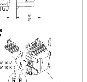
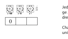
Address Setting
Each communications module in a system must have a unique address ranging from 1 to 99. This is configured using the three rotary switches located on the device. Ensure no two modules share the same address.
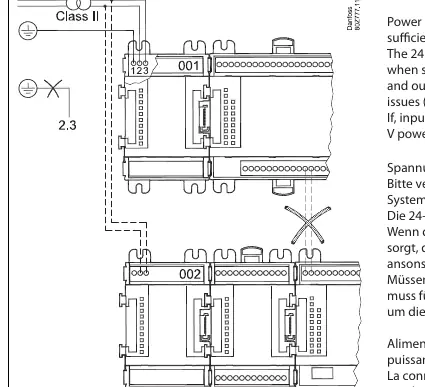
Power Requirements
The module requires a power supply of 24V AC or 18-36V DC. Note that the 24V connection is not galvanically isolated from the inputs and outputs. If sharing a 24V power supply with other communication modules, inputs and outputs must not be shared between those modules to prevent issues such as ground loops. If inputs and outputs must be shared between two or more line-ups, use separate 24V power supplies for each line-up to ensure galvanic isolation.
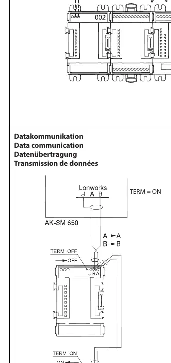
Data Communication
Installation of data communications must comply with the requirements described in literature sheet RC8AC. For units transferring the data signal, the changeover switch must be set to the OFF position. On all other units, the switch must be set to the ON position.
Technical Specifications
- Operating Temperature: -20°C to 55°C (-0°F to 130°F)
- Humidity: 0-95% RH, non-condensing
- Protection Class: IP20 / VBG4
- Power Supply: 24V AC or 18-36V DC
Manufacturer information
Danfoss A/S
Practical help
Common problems
Ground loop issues or communication errors
Ensure separate power supplies are used if inputs and outputs are shared between different line-ups to maintain galvanic isolation.
Data communication failure
Verify the termination switch settings: set to OFF for units transferring the data signal and ON for all other units.
Before use
- Verify the power supply is 24V AC or 18-36V DC.
- Ensure the module is securely mounted on the DIN rail.
- Set a unique address (1-99) using the three rotary switches.
- Check the termination switch position based on the signal flow requirements.
- Ensure power is disconnected before installation or removal.
Specs in practice
- Operating Temperature
- The device operates safely between -20°C and 55°C (-0°F to 130°F).
- Galvanic Isolation
- The 24V connection is not isolated from inputs/outputs; requires separate power supplies if sharing lines to avoid electrical interference.
Images and diagrams
- Rotary switches: Used to set the unique system address from 1 to 99.
- Termination switch: Toggle between ON and OFF depending on whether the unit is at the end of the line or transferring data.
Model compatibility
- Installation of data communications must comply with literature sheet RC8AC.

Manual page author
David Miller
Documentation analyst
Organizes user manual content into clear summaries, with attention to model details, product context, and everyday usability.