Industrial / Communication Modules
User Manual for Assured 104-ICOM-2S Serial Communication Card
Quick guide for the Assured 104-ICOM-2S and 104-COM-2S serial communication cards. Includes installation, jumper configuration, address selection, and programming details.
Table of contents
Manual images
Click an image to enlargeQuick Guide
This document provides instructions for the Assured 104-ICOM-2S and 104-COM-2S serial communication cards. Important: Always power off the computer before installing or removing the board or connecting/disconnecting field cabling to prevent damage and voiding warranties.
Product Overview
The 104-ICOM-2S is a serial communications board designed for PC/104 compatible computers, featuring two isolated serial data ports. The 104-COM-2S is the non-isolated version. Key features include:
- Multipoint transmission using RS422 or RS485 differential line drivers.
- Opto-isolation (on ICOM-2S) for protection against common mode noise.
- Support for 2-wire (Half-Duplex) and 4-wire (Full-Duplex) communication modes.
- Automatic transceiver control for RS485.
- 16-byte transmit/receive buffer (ST16C550 UART).
Specifications
- Serial Ports: Two shielded male D-sub 9-pin IBM AT style connectors.
- Data Rates: 50 to 115,200 baud (up to 460,800 as factory option).
- Isolation: 500 Volts (ICOM-2S).
- Operating Temperature: 0 to +60 °C (Industrial version: -30 to +85 °C).
- Power Required: +5VDC at 200 mA typical, 300 mA maximum.
Hardware Installation

- Configure jumpers for options and base address before installation.
- Remove power from the PC/104 stack.
- Assemble standoff hardware.
- Plug the board onto the PC/104 connector, ensuring proper pin alignment.
- Install I/O cables.
- Verify connections and power up the system.
- Run the provided sample programs to validate installation.
Option Selection (Jumpers)
The board uses jumpers to configure settings:
- A5-A9: Set the board's base address on the I/O bus. Installing a jumper sets the bit to 0; no jumper sets it to 1.
- IRQ3-IRQ15: Set the interrupt level. One IRQ services both serial ports.
- 485A/B and 422A/B: Configure the port mode. Use 485 for 2-wire RS485 (Half Duplex) and 422 for 4-wire RS422 (Full Duplex).
- TRMI and TRMO: Connect on-board RC termination circuits. TRMI is for input lines (4-wire RS422); TRMO is for output/input lines (2-wire RS485).
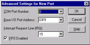
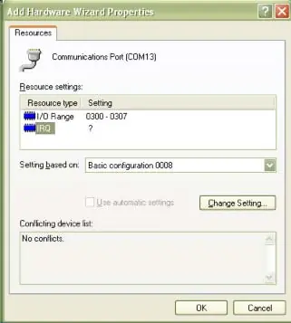
Address Selection
The base address can be selected within the 000-3E0 hex range. Ensure the address does not overlap with other system functions. Use the provided FINDBASE.EXE program to identify available addresses.
Programming
The board uses standard 16550 UART registers. Initialization involves:
- Setting the baud rate divisor (requires setting DLAB high at Base Address +3).
- Setting the Line Control Register (Base Address +3) for word length, stop bits, and parity.
- Setting the Modem Control Register (Base Address +4).
- Flushing receiver buffers.
Reception can be handled via polling or interrupt-driven methods. Transmission in RS485 mode is automatic.
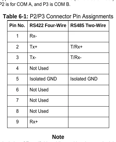
Connector Pin Assignments
The board uses 9-pin D-sub male connectors (P2 for COM A, P3 for COM B). Refer to the pinout table in the manual for specific RS422 and RS485 wiring configurations.
Official resources from the manual
Practical help
Common problems
Unpredictable computer behavior
Check for address overlaps with other installed functions using the FINDBASE.EXE program.
No communication
Verify that the DLAB bit is set to zero after the baud rate divisor is loaded.
Communication noise or ringing
Ensure proper termination jumpers (TRMI/TRMO) are installed according to the wiring mode (RS422/RS485).
Before use
- Install software from the provided CD.
- Configure jumpers for base address (A5-A9) and IRQ.
- Set 485/422 jumpers based on your cabling mode.
- Power off the PC/104 stack before installation.
- Ensure proper alignment of PC/104 pins.
Specs in practice
- RS485 2-wire
- Half-Duplex communication; data travels in both directions but only one at a time.
- RS422 4-wire
- Full-Duplex communication; data travels in both directions simultaneously.
- Base Address
- The starting I/O address for the board; must be unique in the system.
Images and diagrams
- Figure 3-1: Option Selection Map shows the physical location of jumpers for Address, IRQ, 485/422 mode, and Termination.
- Figure 3-2: Simplified Schematic illustrates the termination and bias circuitry for 2-wire and 4-wire connections.
Model compatibility
- Designed for PC/104 compatible computers.
- Supports Windows and DOS environments.
- For WinCE, contact the factory for specific instructions.

Manual page author
Michael Turner
Technical manual editor
Reviews PDF manuals for structure, safety notes, and practical product details so readers can find the right information quickly.