Electronics / Speakers Soundbars
JBL Club 194T Pair Speaker User Guide
Quick installation and technical guide for the JBL Club 194T tweeter set, including mounting options, wiring diagrams, and performance specifications.
Table of contents
Manual images
Jump to the sectionQuick guide from the manual
This document provides installation instructions and technical specifications for the JBL Club 194T tweeter set. It covers multiple mounting configurations and electrical connection procedures to ensure proper integration into your vehicle's audio system.
Installation and Mounting
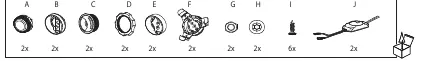
The package includes components for various mounting scenarios. Ensure you have all parts (A-J) before beginning. The tweeters can be installed using different brackets depending on your vehicle's mounting surface requirements.
- Flush Mount: Utilize the provided housing and locking rings to secure the tweeter into a prepared cutout.
- Surface/Angle Mount: Use the appropriate bracket adapters to position the tweeter at the desired angle for optimal sound dispersion.
- Securing: Use the provided screws (I) to fix the mounting brackets firmly to the surface. Ensure the tweeter (A) is securely locked into the bracket (B/C/F).
Wiring and Connections
Proper wiring is essential for speaker longevity and sound quality. Connect the tweeter to the crossover (J) and then to your amplifier or head unit.
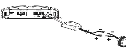
- Observe polarity: Connect positive (+) to positive and negative (-) to negative terminals.
- The crossover (J) must be installed in-line between the audio source and the tweeter to protect the driver from low-frequency damage.
Specifications
- Type: 3/4" (19mm) Edge-Driven dome tweeter
- Power Handling: 50W RMS, 150W peak
- Sensitivity (@ 2.83V): 92dB
- Frequency Response: 3kHz – 20kHz
- Nominal Impedance: 3.0 ohms
Manufacturer information
JBL
Practical help
Common problems
Distorted sound or tweeter failure
Ensure the included crossover (J) is correctly installed. Connecting the tweeter without a crossover will expose it to low frequencies, causing damage.
Loose mounting
Verify that the locking ring (D) or mounting screws (I) are fully tightened. Ensure the mounting surface is flat and rigid.
Before use
- Verify all components (A-J) are present in the box.
- Check the mounting location for sufficient depth (16.8mm clearance required).
- Ensure the mounting hole diameter is appropriate for the chosen installation method (32.5mm).
- Confirm amplifier compatibility with 3.0 ohm impedance speakers.
Specs in practice
- 50W RMS / 150W peak
- The continuous power handling capacity is 50 Watts, with a maximum transient peak handling of 150 Watts.
- 92dB Sensitivity
- Indicates how loud the speaker will play with a standard 2.83V input; higher values are more efficient.
Images and diagrams
- Page 2 shows the exploded view of components and the assembly sequence for different mounting styles.
- Page 3 illustrates the physical installation steps using screws (I) and brackets (F).
- Page 4 provides the wiring diagram showing the connection from the amplifier through the crossover (J) to the tweeter.
Model compatibility
- Designed for automotive audio systems.
- Requires an amplifier capable of driving 3.0 ohm loads.

Manual page author
Michael Turner
Technical manual editor
Reviews PDF manuals for structure, safety notes, and practical product details so readers can find the right information quickly.