Electronics / Speakers & Soundbars
User Manual for JBL Control 10C-VA Series Ceiling Loudspeakers
A comprehensive guide for the JBL Control 10C-VA series, including the 12C-VA, 14C-VA, and 16C-VA models. This manual covers installation, wiring, tap selector settings, painting instructions, and maintenance.
Table of contents
Manual images
Click an image to enlargeQuick guide from the manual
The JBL Control 10C-VA series consists of ceiling loudspeakers designed for high-fidelity sound. Installation can be performed entirely from beneath the ceiling. Key steps include cutting the hole, installing the backing hardware (C-bracket and tile rails), wiring the ceramic terminal block, and securing the speaker using the rotating mounting tabs. Always adjust the tap selector before applying power.
Product Description
The series includes three models:
- Control 12C-VA: 3-inch full-range driver.
- Control 14C-VA: 4-inch woofer and 0.75-inch soft-dome tweeter.
- Control 16C-VA: 6.5-inch woofer and 0.75-inch soft-dome tweeter.
Installation Preparations
Installation hardware is included for both suspended and sheetrock ceilings. For sheetrock, optional pre-installation brackets (New-Construction or Plaster-Ring) are available. Ensure the correct cutout size is used: 167 mm for 12C-VA and 14C-VA, and 225 mm for 16C-VA.
Step-by-Step Installation and Wiring
- Cut the Hole: Cut the circular hole to the specified diameter and pull wiring through.
- Insert Backing Hardware: For suspended ceilings, insert the C-plate and tile rails through the hole. Snap rails into the C-plate tabs and secure them so they rest on the T-grid.
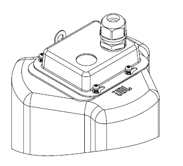
- Remove Terminal Cover: Loosen the 4 screws on the terminal cover plate and remove it.
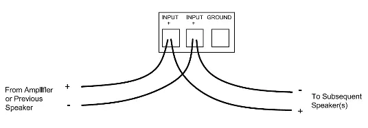
- Connect Wiring: Strip 5 mm of insulation. Insert wires into the ceramic terminal block. Use the side of the terminal without existing wires. Tighten hold-down screws. For loop-out, add a second set of wires in parallel.
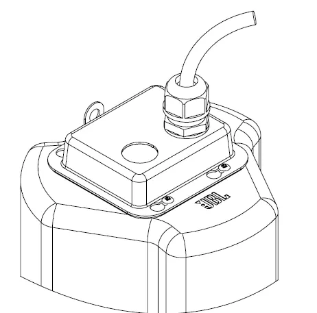
- Re-attach Terminal Cover: Slide the wire through the gland nut, re-attach the cover plate, and tighten the 4 screws. Tighten the gland nut to secure the wire.
- Insert Speaker: Place the speaker into the ceiling. Turn attachment screws counter-clockwise to release mounting tabs, then clockwise to tighten them onto the ceiling surface. Do not over-tighten.
Tap Selector Settings
The rotary switch on the front baffle allows selection between 8-ohm (low impedance) and various 70V/100V distributed system settings. Adjust this setting before applying power and before inserting the grille.
Painting the Speaker
The ABS rim can be painted with latex or oil-based paint. Clean the rim and grille with a light solvent (e.g., mineral spirits) before painting. Do not use abrasives. For the grille, spray lightly with thinned paint, ensuring the mesh does not become clogged.
Maintenance and Safety
No regular maintenance is required. If the grille needs removal, insert two pointed objects into nearby holes and apply slow, even pressure to pull it down. The seismic tab on the back should be used as a secondary support point as required by local construction codes.
Specifications
Specifications vary by model regarding frequency range, power capacity, and sensitivity. Refer to the product specification sheets for detailed data. All models are EN54-24 certified.
Manufacturer information
JBL
Practical help
Common problems
Speaker rattling
Ensure all unused screws on the terminal block are tightened and check if tile rails need dampening material (like neoprene) to eliminate rattles.
Grille difficult to remove
Insert 2 pointed objects (such as push pins) into nearby holes in the grille and apply slow, even pressure to pull down until the section comes out.
Before use
- Verify ceiling type (suspended vs. sheetrock).
- Ensure correct cutout size (167mm for 12C/14C, 225mm for 16C).
- Check if optional pre-installation brackets are needed.
- Ensure amplifier is off before connecting wires.
- Adjust tap selector before applying power.
Specs in practice
- Transformer Taps
- Settings for 70V/100V distributed systems; adjust before applying power.
- Nominal Impedance
- 8 ohms setting for low impedance operation.
Images and diagrams
- Wiring diagrams show how to connect speakers in parallel for distributed systems.
- Installation diagrams illustrate the use of C-brackets and tile rails for suspended ceilings.
Model compatibility
- Not for use in EN54 applications if painted.
- Suitable for use in air handling spaces (UL-2043).

Manual page author
David Miller
Documentation analyst
Organizes user manual content into clear summaries, with attention to model details, product context, and everyday usability.