Electronics / Speakers & Soundbars
Technical Manual for JBL Control 1X/1Xtreme/One
Technical service manual for JBL Control 1X, 1Xtreme, and One speakers. Includes electrical specifications, wiring diagrams, exploded views, and step-by-step instructions for driver removal and replacement.
Quick answers from the manual
Quick answer
- This is a technical service manual for JBL Control 1X, 1Xtreme, and One speakers, containing electrical specifications, wiring diagrams, and instructions for driver removal and replacement. p. 1, 2
Key actions
- Remove the front baffle to access drivers. p. 2
- Use a heat gun to soften adhesive when removing drivers. p. 2
Problems and fixes
Driver removal
Remove grille, unscrew baffle, unclip connectors, and use a heat gun (750°) to soften the adhesive before extracting the driver.
p. 2Maintenance and reset
- Apply adhesive to the outer rim of drivers upon reassembly. p. 2
Technical specifications
| Parameter | Value | Meaning | Pages |
|---|---|---|---|
| Nominal Impedance | 8 Ohms | Standard speaker impedance | p. 1 |
| Max Amp Power | 80 Watts | Maximum recommended amplifier power | p. 1 |
Where to find it in the PDF
- Specifications and Wiring p. 1
- Exploded View and Service p. 2
Table of contents
Manual images
Click an image to enlargeImportant information from the manual
This document serves as a technical service manual for the JBL Control 1X, 1Xtreme, and One speaker models. It provides essential electrical and acoustic specifications, wiring schematics, and detailed service procedures for technicians. Please note that drivers in these units are bonded with adhesive, requiring specific tools and caution during service.
Technical specifications
- Nominal Impedance: 8 Ohms
- Max Amplifier Power: 80 Watts
- Frequency Response: 80Hz to 20kHz
- Sensitivity: 89dB (2.83V @ 1 meter)
- Crossover Frequency: 4000Hz
System components
The system consists of a cabinet, grille, high-frequency transducer (1/2" Titanium laminate, shielded), low-frequency transducer (4" shielded), and a crossover network.
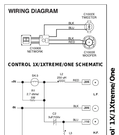
Wiring and schematic
The manual includes a wiring diagram and a schematic for the Control 1X/1Xtreme/One. The wiring diagram illustrates the connection between the C1006X crossover network, the tweeter (C1002X), and the woofer (C1003X).
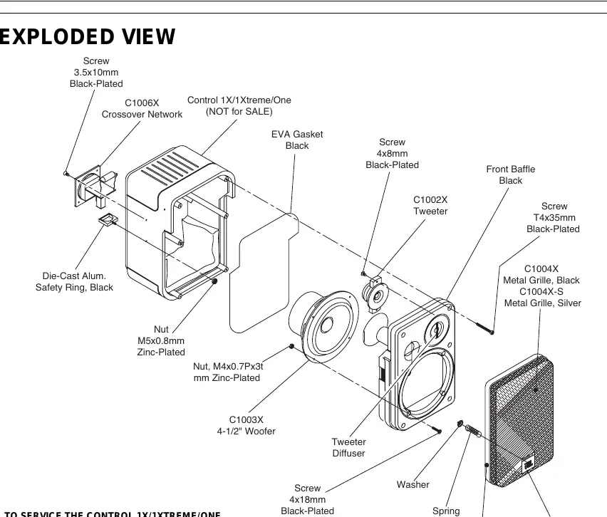
Service and maintenance
The manual provides an exploded view of the speaker assembly and specific instructions for servicing the drivers.
Driver removal
- Remove the grille.
- Remove all (6) 1-3/8" Allen-head screws holding the front baffle to the enclosure.
- Separate the front baffle with drivers from the enclosure.
- Unclip FASTON connectors from both the woofer and tweeter.
- Woofer removal: Remove all (4) machine screws (use long-nosed pliers to hold the rear nut). Apply a heat gun (750°) to the area around the woofer basket until the adhesive softens to extract the woofer.
- Tweeter removal: Remove both (2) Phillips screws. Apply a heat gun (750°) to the area around the inside of the cavity until the adhesive softens to extract the tweeter. Take care not to lose the small clear plastic diffuser.
Driver replacement
Both the woofer and tweeter must have a bead of adhesive applied to the outer rim only upon reassembly. Silicone sealer or rubber-to-metal cement is recommended. Caution: Applying too much heat to one area for too long can warp the front baffle.
Manufacturer information
JBL
Practical help
Common problems
Driver failure or replacement
Requires removing the front baffle and using a heat gun (750°) to soften the adhesive bonding the drivers to the baffle.
Front baffle warping
Avoid applying too much heat to one area for too long when using a heat gun to soften the adhesive.
Before use
- Verify amplifier power rating does not exceed 80 Watts.
- Ensure proper wiring connections as per the provided schematic.
- Check that the system impedance is 8 Ohms.
Specs in practice
- Nominal Impedance
- 8 Ohms; the standard electrical resistance of the speaker system.
- Max Amp Power
- 80 Watts; the maximum recommended power to ensure proper headroom and prevent damage.
Images and diagrams
- Wiring diagram shows the signal path from the crossover network to the tweeter and woofer.
- Exploded view displays the assembly order of the grille, baffle, drivers, and mounting hardware.
Model compatibility
- Drivers are bonded with adhesive; service requires a heat gun.
- Replacement drivers must be re-bonded with silicone sealer or rubber-to-metal cement.

Manual page author
David Miller
Documentation analyst
Organizes user manual content into clear summaries, with attention to model details, product context, and everyday usability.