Electronics / Speakers & Soundbars
Owner's Manual for JBL On Air Control 2.4G Wireless Loudspeaker System
Quick guide for the JBL On Air Control 2.4G wireless speaker system. Includes setup instructions, connection options for home theater or remote audio, wall mounting steps, and technical specifications.
Quick answers from the manual
Quick answer
- The JBL On Air Control 2.4G is a wireless speaker system. Connect the transmitter to your audio source (receiver or portable player) and the active speaker to power. Ensure both units are set to the same ID code for wireless communication. p. 4, 8
Key actions
- Connect to Home Theater p. 5
- Set ID Code p. 8
- Wall Mount Speakers p. 9
First start
- Plug in the transmitter and active speaker. Wait for the top LED to turn solid green, indicating RF lock. p. 6, 7
Problems and fixes
Interference
Change the ID code on both the transmitter and the active speaker.
p. 8Maintenance and reset
- Clean enclosures with a soft cloth and inspect wiring connections at least once per year. p. 10
Technical specifications
| Parameter | Value | Meaning | Pages |
|---|---|---|---|
| Frequency Range | 80Hz – 20kHz | Audio frequency response | p. 11 |
| RF Operating Frequency | 2.4GHz | Wireless transmission frequency | p. 11 |
Where to find it in the PDF
- Safety Precautions p. 3
- Connections p. 5, 6, 7
- Operation p. 8
- Wall and Stand Placement p. 9, 10
- Specifications p. 11
Table of contents
Manual images
Click an image to enlargeQuick guide from the manual
The JBL On Air Control 2.4G is a wireless loudspeaker system designed to add surround speakers to a home theater or to provide audio in remote locations. To ensure proper operation, ensure the transmitter and active speaker are set to the same ID code. The system requires an AC power connection for both the transmitter and the active speaker. When first powered on, the system may take a few seconds to initialize and establish an RF lock (indicated by a solid green LED).
Unpacking the system
Verify that your package includes the following items:
- 1 x Transmitter module
- 1 x Active speaker/receiver (left-channel)
- 1 x Passive speaker (right-channel)
- Power supplies and AC cords for transmitter and active speaker
- Wall-mount brackets for transmitter and speakers
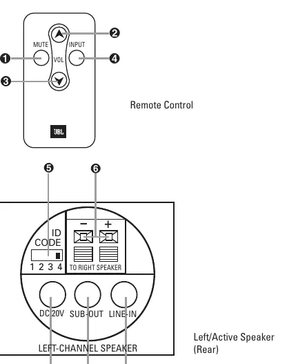
- Remote control
- Interconnect cables (RCA-RCA and RCA-1/8-inch mini plug)
- Speaker wire (10m/33 ft.)
Connections
Application 1: Home Theater Surround
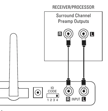
Connect the interconnect cable from your receiver's surround/rear preamp outputs to the input on the transmitter module. Ensure power is off on all components during connection.
Application 2: Remote Locations
Connect your audio source (A/V receiver, portable player, or computer) to the transmitter module using either the RCA preamp outputs or a 1/8-inch stereo mini-jack output. If your source has both, preamp outputs are recommended.
Speaker Connection
Connect the included speaker wire to the push terminals on the active speaker and the passive speaker. Ensure the polarity stripe is used to connect positive (+) to positive (+) and negative (-) to negative (-).
Operation
Adjusting the Volume
In a home theater setup, use your A/V receiver's volume control to balance the output. For remote applications, if the source volume affects the output, set the source volume to approximately half-way (or three-quarters for computers) and use the included remote control for final adjustments.
ID Code
If you experience interference, change the 4-position ID code selector on both the transmitter and the active speaker. Both units must be set to the same position to function.
Local Input
The active speaker features a local input (1/8-inch mini-jack) on the rear. This allows you to connect a portable audio player directly to the speaker. Use the input button on the remote to switch between the wireless source and the local input.
Subwoofer Output
The active speaker includes a subwoofer output. Connect this to a powered subwoofer using a 1/8-inch stereo mini-jack to dual-RCA cable.
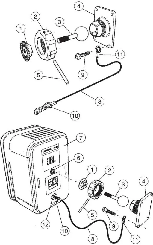
Wall and stand placement
The system includes adjustable wall brackets for the speakers and the transmitter. Ceiling mounting is not recommended. When mounting speakers, ensure the back-up cord is properly attached to prevent the speaker from falling if it detaches from the bracket. The transmitter can be mounted to the wall using the provided bracket and screws.
Maintenance and service
Clean the enclosures with a soft cloth to remove dust or fingerprints. Periodically inspect and clean all wiring connections at least once per year.
Specifications
- Frequency Range: 80Hz – 20kHz
- Amplifier Output: 15 Watts per channel
- Operating Range: Up to 21m (70') depending on conditions
- RF Operating Frequency: 2.4GHz
Manufacturer information
JBL
Practical help
Common problems
No sound output
Check that the transmitter and active speaker are powered on and have established an RF lock (solid green LED). Ensure ID codes match on both units.
Interference during operation
Change the 4-position ID code selector on both the transmitter and the active speaker to a different channel.
Speaker not 'waking up'
Wait a few seconds after plugging in the power; the system requires time to initialize.
Before use
- Verify all components are included in the box
- Ensure power is turned off on all components before connecting
- Check that the transmitter antenna is extended upwards
- Ensure ID code settings match on both transmitter and active speaker
- Verify the polarity of speaker wire connections (+ to +, - to -)
Specs in practice
- RF Operating Frequency
- Operates on the 2.4GHz band, similar to wireless home networks.
- Operating Range
- Up to 21 meters (70 feet), though this varies based on building materials and interference.
- Amplifier Output
- 15 Watts per channel for the active speaker system.
Images and diagrams
- Figure 1: Connecting transmitter to home theater surround preamp outputs
- Figure 3: Connecting speaker wire between active and passive speakers
- Figure 9: Exploded view of wall bracket assembly for speakers
Model compatibility
- Requires source with RCA preamp outputs or 1/8-inch stereo mini-jack output.
- Not recommended for ceiling mounting.
- Subwoofer output is full-range; ensure your powered subwoofer has a low-pass crossover.

Manual page author
Emily Carter
User documentation editor
Prepares concise manual descriptions and highlights the most useful setup, operation, and maintenance information for readers.