Electronics / Speakers & Soundbars
User Manual for Sonance Patio Series System and UA 2-125 Amplifier
Quick guide for the Sonance Patio Series System and UA 2-125 Amplifier. Includes installation steps, wiring diagrams, speaker layout planning, and technical specifications.
Table of contents
Manual images
Click an image to enlargeQuick Guide from the Manual
The Sonance Patio Series System is designed for outdoor entertainment. This manual provides instructions for installing the satellite speakers and subwoofer, wiring the system, and connecting it to the UA 2-125 Amplifier. Professional installation is recommended. Always consult a qualified structural engineer for elevated or suspended deployments.
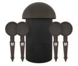
Box Contents
- (4) 3.5” Satellite Speakers
- (4) Attached Speaker Stakes with 1/2” NPS Threading
- (1) 8” In-Ground Subwoofer
- (1) UA 2-125 Amplifier
Speaker Layout Planning
For optimal coverage, place satellite speakers 8 to 10 feet (2.4 - 3.1 meters) apart. The subwoofer should be placed near the center of the satellite speakers. Placing the subwoofer near a wall or solid structure can reinforce low bass frequencies.
Installation and Wiring
Recommended Wire: 14/4 direct-burial speaker wire is recommended. Low voltage lighting wire can also be used if run as two pairs (one for each channel).
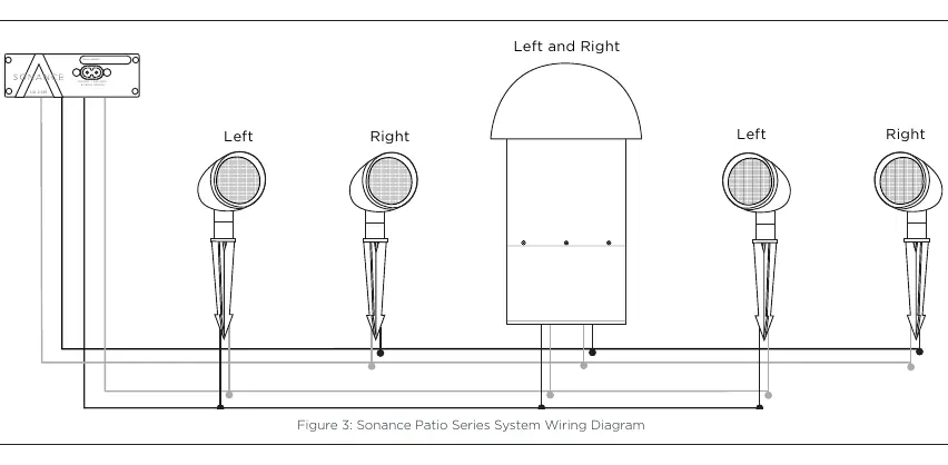
- Place the four satellites and one subwoofer in their approximate final locations.
- Dig a 4” to 5” trench for the speaker wires, checking local codes for limitations.
- Run the speaker wire from the amplifier to the first speaker location.
- Use a round cable stripper to expose the 4 individual color-coded wires.
- Create a 6” loop of wire at each speaker location and secure with a wire tie for strain relief.
- Strip 3/4 inch of insulation from the wires.
- Connect wires using the provided silicone-filled wire nuts. Ensure no copper is exposed.
- Wiring Configuration: Use a parallel/daisy chain configuration. Red (+) and Black (-) are for the Right channel; White (+) and Green (-) are for the Left channel.
Important: Ensure only two satellite speakers are connected to each amplifier channel to avoid an unacceptable load that could damage the amplifier. Do not let stray '+' and '-' strands touch, as this will cause a short-circuit.
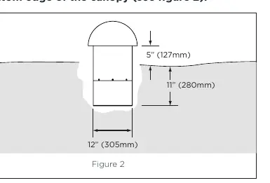
Subwoofer Installation
The subwoofer requires a burial space approximately 12” in diameter and 11” deep. Ensure there is roughly 5” of exposed subwoofer enclosure from the ground surface to the bottom edge of the canopy. The subwoofer can be connected at any point in the daisy chain.
Technical Specifications
- Frequency Response: 40Hz - 20kHz (+/-3dB)
- Impedance: 8 ohms nominal per channel
- Power Handling: 50 watts minimum; 150 watts system
- Dispersion: 60-degree dispersion with an optimum listening area 8’-20’ from satellites
- Enclosure Material: Non-corroding, high-heat ABS
Warranty
This product includes a limited three (3) year warranty from the date of purchase. Contact your authorized Sonance Dealer/Installer or Sonance Customer Service at 949-492-7777 for service. A return merchandise number (RMA) is required for warranty claims.
Manufacturer information
JBL
Practical help
Common problems
No low frequency sound
Ensure the subwoofer's dual voice coils are connected correctly (positive and negative wires for both left and right channels).
Short-circuit or amplifier damage
Ensure no stray '+' and '-' wire strands are touching each other.
Unacceptable load on amplifier
Verify that only two satellite speakers are connected to each amplifier channel.
Before use
- Verify 14/4 direct-burial speaker wire is available.
- Ensure wire strippers and a round cable stripper are on hand.
- Plan speaker layout with 8-10 feet spacing.
- Check local codes for trenching limitations.
- Ensure you have silicone-filled wire nuts (provided).
Specs in practice
- Frequency Response
- 40Hz - 20kHz (+/-3dB) range.
- Power Handling
- 50 watts minimum; 150 watts system capacity.
Images and diagrams
- Wiring Diagram: Illustrates the daisy-chain configuration for connecting satellite speakers and the subwoofer to the amplifier.
- Subwoofer Burial: Shows the required 12-inch diameter and 11-inch depth for the subwoofer, with 5 inches of exposed enclosure.
Model compatibility
- Requires 14/4 direct-burial speaker wire.
- Compatible with 2-conductor wire if run in pairs (one pair per channel).

Manual page author
Michael Turner
Technical manual editor
Reviews PDF manuals for structure, safety notes, and practical product details so readers can find the right information quickly.