Electronics / Speakers & Soundbars
User Manual for JBL Control 10 Series Ceiling Loudspeakers
Quick guide for installing and configuring JBL Control 10 Series ceiling speakers (12C/T, 14C/T, 16C/T, 18C/T). Includes wiring diagrams, cutout dimensions, mounting instructions, and tap selector settings.
Table of contents
Manual images
Click an image to enlargeQuick guide from the manual
The JBL Control 10 Series ceiling loudspeakers are designed for high-fidelity sound in various environments. Installation can be performed entirely from beneath the ceiling. Key requirements include using the included C-plate and tile rails for suspended ceilings, and ensuring the tap selector is set correctly before installing the grille. Always use the seismic tab as a secondary support point if required by local building codes.
Product Description
The series includes four models with varying driver sizes:
- Control 12C/T: 3-inch full-range driver.
- Control 14C/T: 4-inch woofer and 3/4-inch tweeter.
- Control 16C/T: 6.5-inch woofer and 3/4-inch tweeter.
- Control 18C/T: 8-inch woofer and 1-inch tweeter.
Installation Preparations
Before starting, ensure you have the correct cutout size for your model:
- Control 12C/T & 14C/T: 167 mm (6.6 in)
- Control 16C/T: 225 mm (8.8 in)
- Control 18C/T: 282 mm (11.1 in)
For suspended ceilings, the included C-plate and tile rails must be used to support the speaker. For sheetrock ceilings, optional pre-installation brackets (New-Construction or Plaster-Ring) are available but not strictly required if the C-bracket is used to spread clamping force.
Step-by-Step Installation
- Cut the Hole: Use the specified cutout diameter for your model and pull the wiring through.
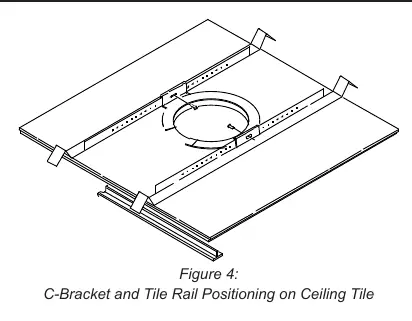
- Insert Backing Hardware: For suspended ceilings, insert the C-plate through the hole, snap the tile rails into the C-plate tabs, and secure them so the ends rest on the T-channel grid.
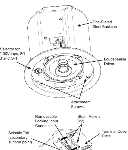
- Connect Wiring: Strip insulation back 5 mm. Insert wires into the removable locking connector and tighten the hold-down screws.
- Open Strain Relief: Loosen the set screws and sliding cover on the backcan to prepare for cable entry.
- Insert Speaker: Place the speaker into the ceiling cutout until the front rim touches the ceiling.
- Tighten Mounting Tabs: Turn attachment screws counter-clockwise 1/2 turn to release tabs, then clockwise to tighten them against the ceiling surface. Do not overtighten.
Wiring
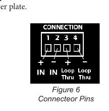
The removable connector has 4 terminals. Pins 1 & 2 are the input. Pins 3 & 4 are loop-through connections for subsequent speakers. You can choose between a parallel hookup (where disconnecting one speaker does not affect others) or a loop-through hookup (where disconnecting one speaker disconnects subsequent ones).
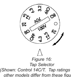
Tap Selector
The rotary switch is located on the front baffle. Adjust this before installing the grille. Turn counter-clockwise to set to 8Ω (low impedance) or clockwise to select 70V/100V distributed system tap settings.
Painting
The speaker rim and grille can be painted. Use a light solvent to clean the surface first. Apply two thin coats of latex or oil-based paint. Use the included clear plastic paint shield to protect the drivers while painting the rim.
Maintenance
No regular maintenance is required. There are no user-serviceable parts inside. If service is needed, contact an authorized JBL Service Center.
Manufacturer information
JBL
Practical help
Common problems
Speaker rattling
Tighten any unused screws on the connector and ensure the strain relief fitting is fully tightened.
Grille falling out
Ensure the grille is pressed firmly into place around the entire perimeter. If it needs removal, use two pointed objects in the grille holes to pull it out.
Ceiling tile vibration
Place neoprene or other dampening material under the tile rails or edges of the tiles.
Before use
- Verify the ceiling type (suspended vs. sheetrock).
- Check the required cutout diameter for your specific model.
- Ensure all included support brackets (C-plate, tile rails) are used for suspended ceilings.
- Set the tap selector to the desired impedance (8Ω) or voltage (70V/100V) before installing the grille.
- Connect the safety line to the seismic tab if required by local building codes.
Specs in practice
- 70V/100V Taps
- Settings for distributed audio systems allowing multiple speakers on one line.
Images and diagrams
- Figure 6: Connector pinout showing input (1 & 2) and loop-through (3 & 4) terminals.
- Figure 14: Correct orientation of C-ring and tile rails above the ceiling tile.
Model compatibility
- Suitable for use in air handling spaces (UL-2043 compliant).
- Compatible with standard 24-inch or 600mm wide ceiling tiles.

Manual page author
Michael Turner
Technical manual editor
Reviews PDF manuals for structure, safety notes, and practical product details so readers can find the right information quickly.