Garden / Outdoor
Assembly and User Guide for KCT 160/200L Twin Wheel Barrow
A comprehensive assembly guide for the KCT 160/200L Twin Wheel Barrow. Includes a detailed parts list and step-by-step instructions for frame assembly, wheel installation, and securing all components for safe operation.
Table of contents
Manual images
Click an image to enlargeQuick Guide for Assembly
The KCT 160/200L Twin Wheel Barrow requires full assembly before use. The most critical safety instruction is to ensure all bolts are secured tightly before use. Follow the step-by-step assembly instructions carefully, ensuring the correct bolts (75mm, 45mm, or 25mm) are used for each specific connection as detailed in the steps below.
Parts List
Before beginning assembly, verify that you have all the following components:
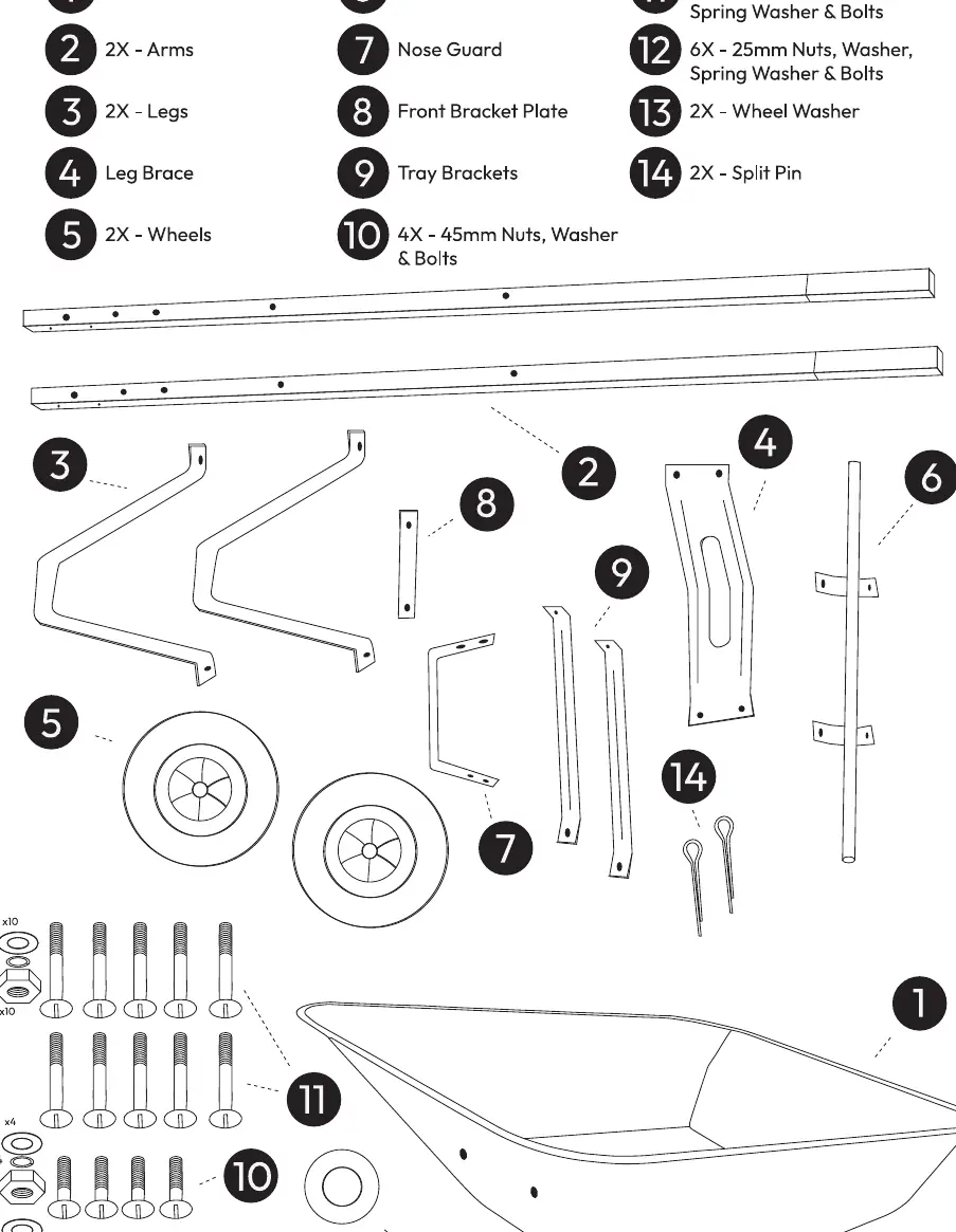
- 1: Plastic Base
- 2: 2x Arms
- 3: 2x Legs
- 4: Leg Brace
- 5: 2x Wheels
- 6: Axle
- 7: Nose Guard
- 8: Front Bracket Plate
- 9: Tray Brackets
- 10: 4x 45mm Nuts, Washer & Bolts
- 11: 10x 75mm Nuts, Washer, Spring Washer & Bolts
- 12: 6x 25mm Nuts, Washer, Spring Washer & Bolts
- 13: 2x Wheel Washer
- 14: 2x Split Pin
Assembly Instructions
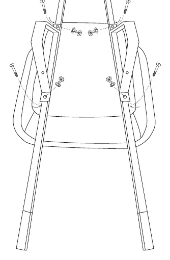
Step 1: Frame Assembly
Align the arms (2) onto the plastic base with the handles pointing towards the back end. Place the legs on top of the arms, ensuring the leg brace holes face the rear of the base. Align all bolt holes and secure both the legs and arms to the plastic base using four 75mm (11) nuts and bolts.
Step 2: Nose Guard
Attach the nose guard (7) to the front of the arms using four 45mm (10) nuts and bolts through the side.
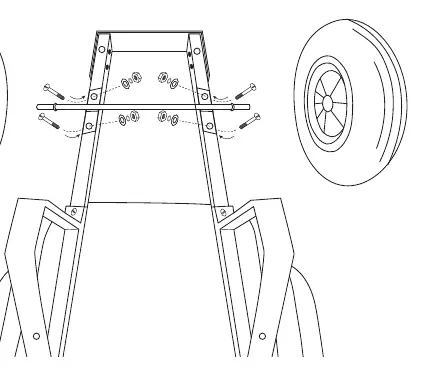
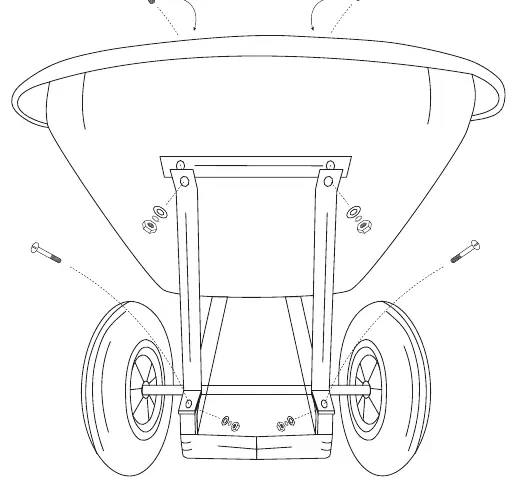
Step 3: Axle and Wheels
Secure the axle (6) onto the bottom of the arms at the front using four 75mm (11) nuts and bolts. Slide the wheels (5) onto each end of the axle.
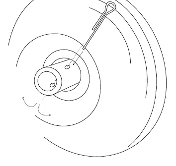
Step 4: Securing Wheels
Secure the wheels in place using the wheel washer (13) first, followed by the split pin (14). Insert the split pin into the holes shown and split the two sides of the pin where it exits to lock it in place. Repeat this process for the other wheel.
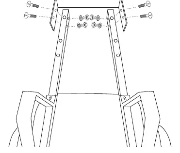
Step 5: Leg Brace
Place the leg brace (4) onto the back side of the legs. Line up the holes and fasten in place using four 25mm (12) nuts and bolts.
Step 6: Tray Brackets
Secure the bottom side of the tray brackets (9) to the legs using two 75mm (11) nuts and bolts. Place the front bracket plate (8) along with the other ends of the tray brackets to the plastic base and secure together using two 25mm (12) nuts and bolts.
Practical help
Common problems
Wobbly or unstable frame
Ensure all bolts are tightened securely. Check that the leg brace and tray brackets are properly aligned and fastened.
Wheel coming off or loose
Verify that the split pin is correctly inserted through the axle hole and that the ends are bent (split) to prevent the washer and wheel from sliding off.
Before use
- Verify all parts are present according to the parts list.
- Ensure all bolts are tightened securely before use.
- Check that the split pins are correctly inserted and bent to secure the wheels.
- Confirm the leg brace is securely fastened to the legs.
- Ensure the nose guard is firmly attached to the front of the arms.
Specs in practice
- 75mm Nuts/Bolts
- Used for primary structural assembly, including arms, legs, axle, and tray brackets.
- 45mm Nuts/Bolts
- Specifically used for attaching the nose guard to the arms.
- 25mm Nuts/Bolts
- Used for securing the leg brace and the front bracket plate.
Images and diagrams
- The parts list diagram provides a visual reference for identifying the different bolt lengths and components.
- Step-by-step diagrams illustrate the exact placement of hardware for each connection point.

Manual page author
Emily Carter
User documentation editor
Prepares concise manual descriptions and highlights the most useful setup, operation, and maintenance information for readers.