Industrial / Pumps & Motors
User Manual for MARCO 16463515-UP8 Self-Priming Electric Pump
Quick guide for the MARCO 16463515-UP8 self-priming electric pump. Includes installation steps, electronic pressure sensor LED diagnostics, maintenance, and technical specifications.
Table of contents
Manual images
Click an image to enlargeQuick guide from the manual
The MARCO 16463515-UP8 is a self-priming electric pump designed for transferring fresh and salt water. It features an integrated electronic pressure sensor for flow control. Important: This pump is not ATEX certified and must not be used in potentially explosive atmospheres or with flammable liquids, solvents, or corrosive chemicals. Installation and maintenance must be performed by qualified personnel.
Installation
The pump can be mounted in any position. Ensure the following during installation:
- Preliminary Checks: Inspect for transport damage and clean inlet/outlet ports. Verify electrical supply matches the pump specifications.
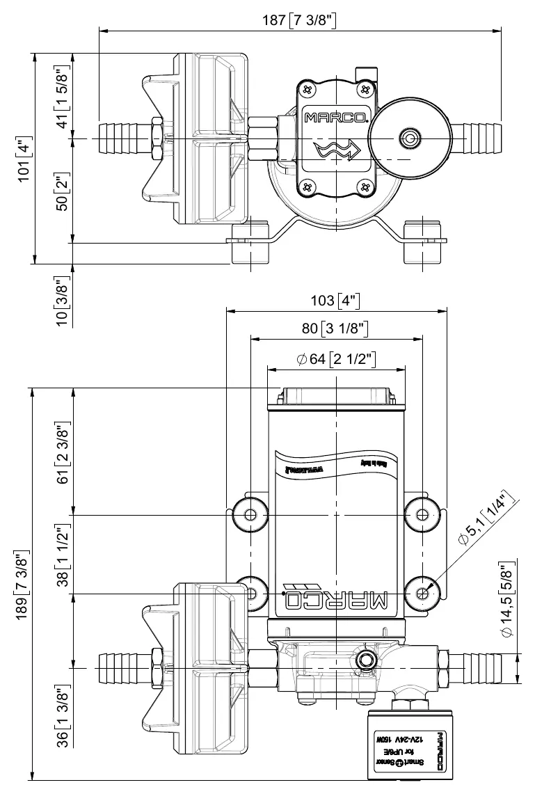
- Positioning: Fix the pump using suitable screws. Ensure the flow direction matches the arrow on the top plate.
- Tubing: Use flexible tubing on the outlet side (at least 1m recommended). Avoid choking inlet/outlet tubes. An inlet filter is recommended for fluids with impurities.
- Electrical Connection: Connect the positive pole (+) to the red wire and the negative pole (-) to the black wire. A correctly rated fuse must be installed as per the motor label. Use anti-vibration rubber fittings supplied with the kit.
Operation
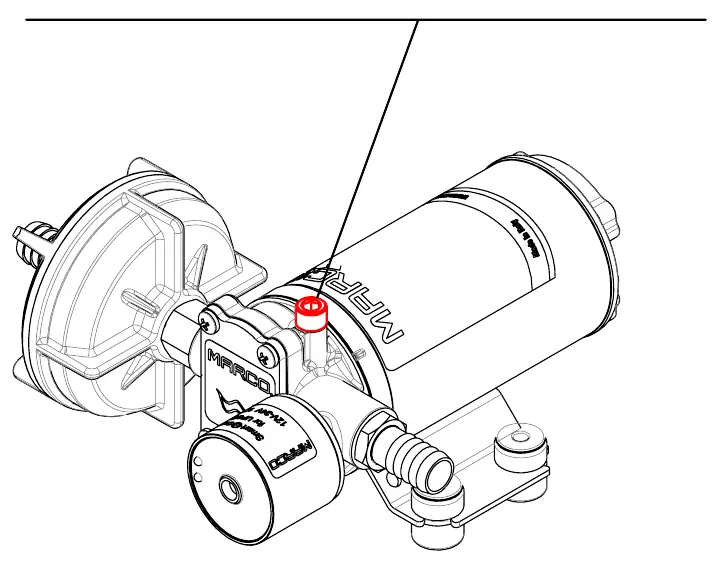
Air Vent Valve: When starting the pump or emptying the tank, slightly open the small valve to let air out and facilitate priming. Close the valve once the pump is operating.
Electronic Pressure Sensor: The pump uses a microprocessor to control speed. LED indicators provide status updates:
- Blue LED: Indicates liquid presence (on) or priming mode (flashing).
- Multicolored LED: Indicates pressure status (Green: target reached; Yellow: trying to reach target; Red: error/overload).
- Combined Warnings: Red/Blue alternating indicates dry run protection; Yellow/Blue blinking indicates wrong voltage.
Maintenance
- Filter: Frequently check and clean the inlet filter.
- Chamber: Check monthly for foreign matter.
- Wiring: Check monthly that electrical connections are secure.
- Storage: If the pump will be inactive for 30+ days, flush with fresh water and loosen the front plate screws.
Troubleshooting
If the pump fails to prime, check for excessive height above fluid level, air leaks in suction pipes, clogged filters, or obstructions. If the pump stops, check the battery voltage, fuse status, and for foreign matter in the pump body.
Practical help
Common problems
Pump will not prime
Check for excessive height above fluid level, air leaks in suction pipes, clogged filters, or obstructions in the pipes.
Pump stopped or will not start
Check battery voltage, inspect for a blown fuse, or check for foreign matter inside the pump body.
Red and Blue LEDs blink alternatively
The pump has run without liquid. Reboot the circuit or press the Reset button.
Yellow and Blue LEDs blink together
Incorrect voltage detected. Check power supply and wire section.
Before use
- Inspect for transport damage.
- Clean inlet and outlet ports.
- Verify electrical power supply matches specifications.
- Install a correctly rated fuse.
- Mount anti-vibration rubber fittings.
- Ensure inlet filter is installed if fluid contains impurities.
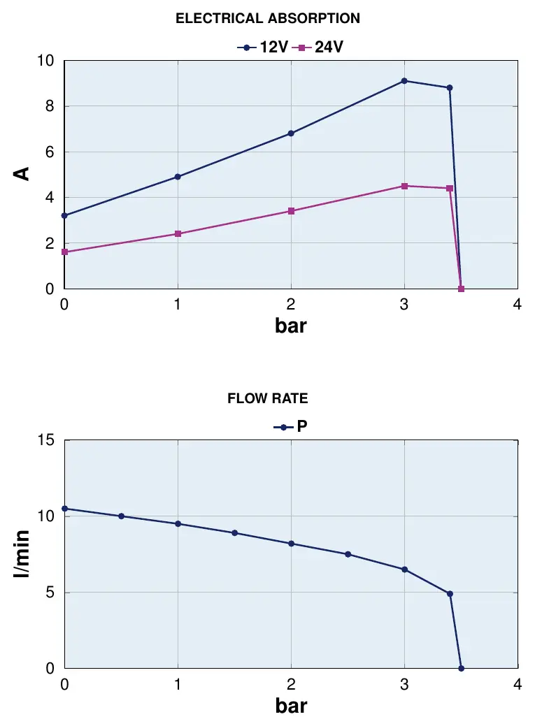
Specs in practice
- Max Flow Rate
- 11 l/min (2.9 gpm).
- Max Pressure
- 3.5 bar (50.8 psi).
- IP Protection
- IP67 (dust tight and protected against immersion).
Images and diagrams
- Exploded view shows component assembly and spare parts list.
- Electrical absorption graph shows current draw (A) vs pressure (bar) for 12V and 24V.
- Flow rate graph shows performance (l/min) vs pressure (bar).
Model compatibility
- Designed for fresh and salt water.
- Not ATEX certified; do not use in explosive atmospheres.
- Do not use with solvents, chemicals, or flammable liquids.
- Requires accumulator tank (min 0.5L) for short, rigid pipes or solenoid valves.

Manual page author
Emily Carter
User documentation editor
Prepares concise manual descriptions and highlights the most useful setup, operation, and maintenance information for readers.