Tools / Welding Equipment
User Manual for Miller Millermatic 130XP Welder
Quick guide for the Miller Millermatic 130XP MIG welder. Includes installation steps, welding settings, maintenance procedures, and troubleshooting tips.
Table of contents
Manual images
Click an image to enlargeQuick Guide from the Manual
The Miller Millermatic 130XP is a MIG welding power source designed for light industrial use. It operates on 115V, 60Hz, single-phase power. Key safety precautions include wearing proper protective gear (welding helmet, gloves, protective clothing), ensuring proper ventilation to avoid fumes, and preventing electric shock by not touching live electrical parts. Always ensure the unit is properly grounded.
Installation
Proper installation is critical for safe operation:
- Location: Place the unit in a location with adequate ventilation and away from flammable materials. Ensure a 115V, 20A individual branch circuit is available.
- Work Clamp: Connect the work clamp to the workpiece to ensure a good metal-to-metal contact.
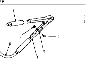
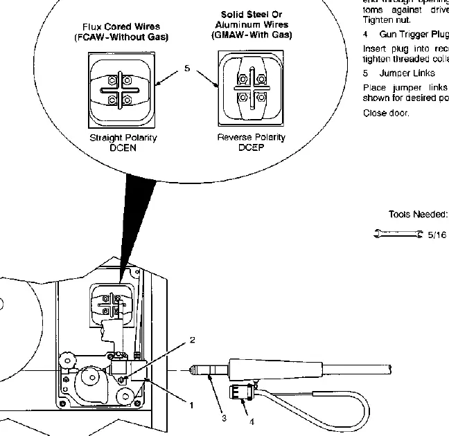
- Welding Gun: Insert the gun into the drive assembly, tighten the securing nut, and connect the trigger plug. Ensure the polarity (DCEP for solid steel/aluminum, DCEN for flux-cored) is set correctly using the jumper links.
- Gas Supply: If using shielding gas, connect the gas hose to the regulator/flowmeter on the cylinder. Ensure the cylinder is secured in an upright position.
- Wire Spool: Install the wire spool and adjust the hub tension so that the spool turns with slight resistance.
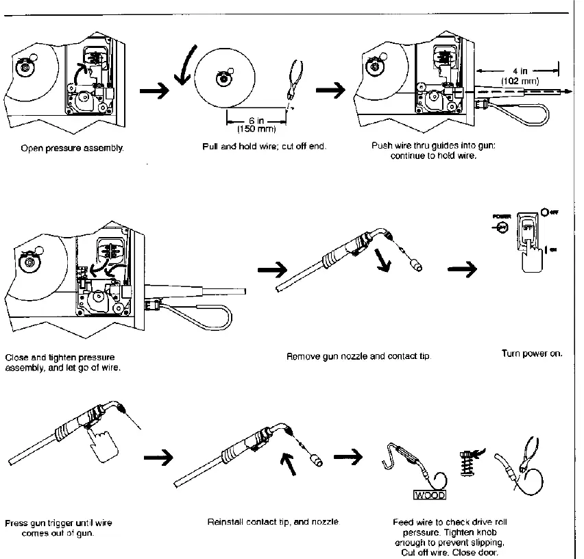
- Drive Roll and Threading: Choose the correct drive roll for the wire type. Thread the wire through the inlet guide, over the drive roll, and into the gun. Press the gun trigger to feed the wire through the gun until it emerges from the tip.
Operation
The control panel features:
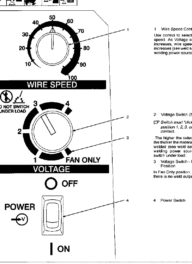
- Wire Speed Control: Adjusts the wire feed speed.
- Voltage Switch: A 5-position switch to select the voltage range. Higher numbers are for thicker materials. Do not switch under load.
- Power Switch: Turns the unit ON or OFF.
Maintenance
Regular maintenance ensures longevity:
- Routine: Every 3 months, replace unreadable labels, repair/replace cracked cables, and clean/tighten weld terminals. Every 6 months, blow out or vacuum the inside of the unit and apply a light coat of oil/grease to the drive motor shaft.
- Drive Motor Fuse: If the drive motor is inoperative, check fuse F1 on the circuit board.
- Gun Maintenance: Regularly clean or replace the contact tip and gun liner if wire feeding becomes erratic.
Troubleshooting
If you encounter issues, consult the following:
- No weld output/wire feed: Check power cord connection, building fuse/circuit breaker, gun trigger connection, and power switch position.
- Excessive Spatter: Check wire feed speed (too high), voltage (too high), electrode extension (too long), dirty workpiece, or insufficient shielding gas.
- Porosity: Check for shielding gas leaks, dirty workpiece, or incorrect gas type.
- Burn-Through: Reduce heat input by lowering voltage or wire feed speed, and increase travel speed.
Welding Guidelines
For best results, maintain a proper gun angle (0-15 degrees) and electrode extension (stickout) of 1/4 to 1/2 inch. Use the provided weld parameter charts to select the appropriate voltage and wire speed based on material thickness and wire type.
Practical help
Common problems
No weld output; wire does not feed; fan does not run
Secure power cord plug in receptacle, check building line fuse or reset circuit breaker, secure gun trigger plug, and ensure power switch is in ON position.
Excessive spatter
Select lower wire feed speed, lower voltage range, use shorter electrode extension, clean workpiece, or increase shielding gas flow.
Porosity (small cavities in weld)
Increase shielding gas flow, check gas hoses for leaks, clean workpiece, or ensure wire extension is not too far out of nozzle.
Burn-through
Select lower voltage range, reduce wire feed speed, and increase travel speed.
Before use
- Ensure 115V, 20A circuit is available.
- Check work clamp connection for good metal-to-metal contact.
- Verify wire type and diameter match the installed drive roll.
- Check shielding gas supply and regulator settings.
- Ensure gun trigger is properly connected.
- Wear appropriate welding helmet and protective clothing.
Specs in practice
- Rated Output
- 90A @ 18V, 20% Duty Cycle.
- Amperage Range
- 30-130A.
- Wire Feed Speed
- 220-700 IPM (Inches Per Minute).
Images and diagrams
- Installation diagrams show proper connection of work clamp, gun, gas supply, and wire spool.
- Maintenance diagrams illustrate drive roll replacement, gun liner cleaning, and contact tip replacement.
Model compatibility
- Compatible with M-10 Gun.
- Supports solid/stainless steel (.023-.030 in) and flux cored/aluminum (.030-.035 in) wires.

Manual page author
Michael Turner
Technical manual editor
Reviews PDF manuals for structure, safety notes, and practical product details so readers can find the right information quickly.