Power / Uninterruptible Power Supplies
User Manual for Milleteknik SINUS-1100-FLX UPS
Comprehensive user manual for the Milleteknik SINUS-1100-FLX Uninterruptible Power Supply. Includes installation, wiring diagrams, commissioning steps, alarm configurations, and technical specifications.
Table of contents
Manual images
Click an image to enlargeQuick guide from the manual
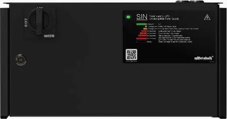
The Milleteknik SINUS-1100-FLX is an off-line UPS designed for security systems, camera surveillance, and door control. Installation must be performed by a qualified person. Always disconnect from the mains before installation or service. Wait one minute after disconnecting power before opening the unit due to high voltage.
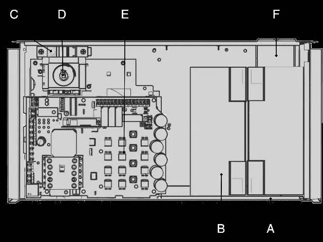
Component Overview
The unit consists of a powder-coated sheet metal cabinet containing batteries, an automatic battery fuse, a main switch, a motherboard, and cable entries. Batteries must be placed according to the provided diagram.
Installation and Mounting
The unit can be mounted on a wall or in a 19-inch rack. Brackets must be positioned backwards for wall mounting and at the front for rack mounting. Use appropriate screws (not included).
Connection
Battery Connection: Connect battery wiring to the automatic fuse and motherboard as shown in the wiring diagram. Ensure correct polarity (B1+, B1-, B2+, B2-).
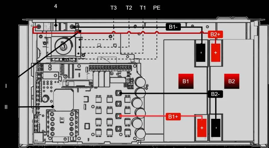
Mains Connection: Connect incoming mains phase to terminal T2, zero to T1, and protective earth to PE. It is recommended to install a load disconnector (circuit breaker) on the incoming cable for safety.
Commissioning
- Turn the isolation switch to "0" and open the cabinet.
- Connect input/output cables, alarm, and switch on the battery circuit breaker.
- Close the cabinet and turn the isolation switch to "1".
- Connect to the mains.
- The system will start automatically; the LED on the cabinet door will flash until it turns steady green.
Alarms and Status Indicators
The front panel features an LED indicator for status. A steady green light indicates normal operation. Flashing patterns indicate specific faults:
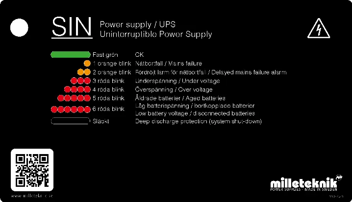
- 1 orange flash: Mains failure.
- 2 orange flashes: Delayed mains failure alarm.
- 3 red flashes: Undervoltage.
- 4 red flashes: Overvoltage.
- 5 red flashes: Aged batteries.
- 6 red flashes: Low battery voltage or disconnected batteries.
Maintenance and Self-Test
The unit performs automatic weekly self-tests, including battery aging tests and inverter tests. If an alarm occurs, check the fuses and battery voltage. Replace batteries if the capacity drops below 80%.
Practical help
Common problems
Alarm for aged battery
Replace batteries if capacity has dropped below 80%.
Incorrect charging voltage
Check charging voltage (27.3V) and fuses.
Inverter fault
Check fuses in the unit.
Before use
- Ensure installation is performed by a qualified person.
- Disconnect from mains during installation.
- Verify battery connections (B1+, B1-, B2+, B2-).
- Ensure load disconnector is installed.
- Check that the unit is properly mounted (wall or 19-inch rack).
Specs in practice
- Max operating power
- 1100 W / 1500 W
- Enclosure class
- IP 32
Images and diagrams
- Component Overview: Shows location of batteries, fuses, and motherboard.
- Wiring Diagram: Details battery and mains connections.
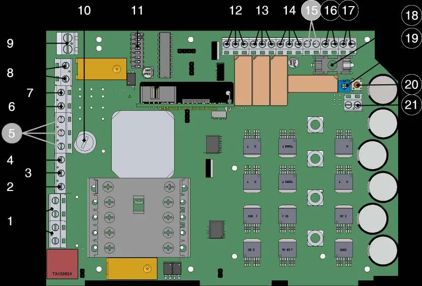
- Motherboard Layout: Identifies terminals for alarms and outputs.
Model compatibility
- Not intended for emergency lighting control.
- Batteries are not included.

Manual page author
David Miller
Documentation analyst
Organizes user manual content into clear summaries, with attention to model details, product context, and everyday usability.