Home Appliances / Range Hoods
nVent HOFFMAN CCFR20 Cable Entry Gland Plate Round Modular Instruction Manual
Quick guide for the nVent HOFFMAN CCFR20 modular cable entry gland plate, covering installation steps, cutout dimensions, torque requirements, and UL compliance conditions.
Table of contents
Manual images
Jump to the sectionQuick guide from the manual
This document provides installation instructions for the nVent HOFFMAN CCFR series modular cable entry gland plates. It details the assembly process, required cutout dimensions, and torque specifications for various models (CCFR20 through CCFR63). Users must adhere to the specified torque settings and UL 508A conditions for safe operation.
Installation and Assembly
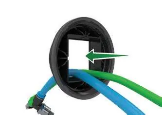
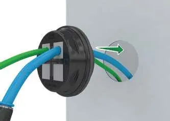
- Guide the cables through the frame.
- Click the inlay into position.
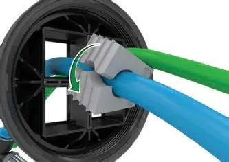
- Attach the seals to the cables.
- Push the seals all the way in.
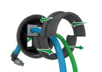
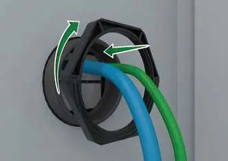
- Assemble the locking adapter.
- Screw the locking adapter into the outer frame.
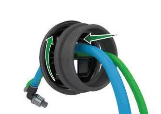
- Mount the assembly from the outside.
- Assemble the counter nut.
- Screw the counter nut on from the inside.
Safety and Compliance
According to UL Standard 508A, the following conditions apply:
- Use M5 stainless steel screws (AISI type 304 or 316).
- Maximum end-use temperature for UL applications is 50°C (52°F).
- Operating temperature range: -40°C to 120°C (-40°F to 248°F) static.
Technical Specifications
The following table outlines the cutout requirements and torque settings for each model:
- CCFR20/25/32: Cutout diameter 20.3mm/25.3mm/32.3mm; Torque 3 Nm (26 in-lb).
- CCFR40/50/63: Cutout diameter 40.4mm/50.4mm/63.4mm; Torque 7 Nm (62 in-lb).
Manufacturer information
nVent HOFFMAN
Practical help
Common problems
Improper seal fit
Ensure seals are pushed all the way into the frame after being attached to the cables.
Loose assembly
Verify that the locking adapter and counter nut are tightened to the specified torque (3 Nm or 7 Nm depending on the model).
Before use
- Verify the correct model (CCFR20-63) for your application.
- Ensure the mounting surface cutout matches the required diameter (D).
- Confirm availability of M5 stainless steel screws (AISI 304/316) for installation.
- Check that the operating environment temperature remains within -40°C to 120°C.
Images and diagrams
- Steps 1-4: Cable insertion and seal placement.
- Steps 5-6: Locking adapter assembly.
- Steps 7-9: Final mounting and securing with the counter nut.
Model compatibility
- Compatible with specific divider options (CCFD1, CCFD2, CCFD4) for models CCFR40, CCFR50, and CCFR63.

Manual page author
Michael Turner
Technical manual editor
Reviews PDF manuals for structure, safety notes, and practical product details so readers can find the right information quickly.