Tools / Generators
User Manual for Palmer PWT12IEC Pedalboard Power Supply
Quick guide for the Palmer PWT12IEC universal 12-output pedalboard power supply. Includes setup, connection details, technical specifications, and safety warnings.
Table of contents
Manual images
Jump to the sectionQuick guide from the manual
The Palmer PWT12IEC is a universal power supply unit designed for effect pedals. It features 12 isolated DC outputs, one non-isolated high-current DC output, and USB-A/USB-C charging ports. The unit is powered directly via a standard IEC cable, eliminating the need for an external power brick.
Connections and Operating Elements
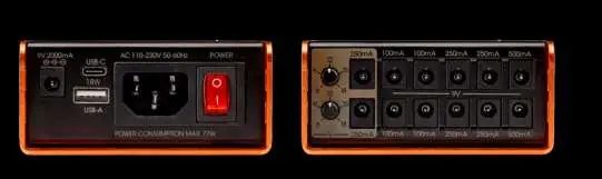
- AC INPUT: IEC connection for power supply.
- POWER: Rocker switch with indicator light for turning the unit on and off.
- DC OUTPUT (Non-isolated): 9V output with up to 2000mA for high-current devices.
- USB: USB-C and USB-A ports (up to 18W total) for charging mobile devices.
- OUTPUT 1 AND 2: Isolated outputs with potentiometers for adjustable voltage (6V to 18V, 250mA max).
- OUTPUT 3 TO 6: Isolated 9V outputs (100mA max each).
- OUTPUT 7 TO 10: Isolated 9V outputs (250mA max each).
- OUTPUT 11 AND 12: Isolated 9V outputs (500mA max each).
Mounting
The power supply housing includes mounting holes on the base plate and side panels. This allows for secure attachment to a pedalboard using accessories like cable ties.

Safety Instructions
- Ensure the polarity of the effect pedal matches the power supply (center-negative).
- Verify that the output voltage of the power supply matches the input voltage required by the effect pedal to prevent overvoltage damage.
- Do not connect devices requiring AC power to the DC outputs.
- Keep the device away from children; it contains small parts and packaging materials that pose a choking hazard.
Technical Data
- Input Voltage: AC 100 - 240 V
- Total Isolated Outputs: 12
- Output Connections: 2.1 x 5.5 mm
- Polarity: Center-negative
- Operating Temperature: 0°C to 40°C
Practical help
Common problems
Effect pedal malfunction or damage
Verify that the pedal's input polarity matches the power supply's center-negative configuration.
Damage due to overvoltage
Ensure the selected output voltage on the power supply matches the specific voltage requirement of the effect pedal.
Damage to power supply or pedal
Do not connect devices designed for AC power to the DC outputs of this unit.
Before use
- Check that the package contains the power supply, IEC cable, DC cables, and rubber feet.
- Verify the voltage requirements of all effect pedals to be connected.
- Confirm that all pedals use center-negative polarity.
- Ensure the power switch is in the OFF position before connecting devices.
- Set the required voltage for outputs 1 and 2 BEFORE connecting the effect device.
Specs in practice
- Non-isolated DC Output
- Fixed 9V output capable of delivering up to 2000mA for high-current devices.
Images and diagrams
- The front panel contains the AC input, power switch, USB ports, and the non-isolated 2000mA DC output.
- The top panel features the 12 isolated DC outputs, grouped by voltage and current capacity.
Model compatibility
- All DC outputs are wired with the positive pole outside and the negative pole inside (center-negative).

Manual page author
Michael Turner
Technical manual editor
Reviews PDF manuals for structure, safety notes, and practical product details so readers can find the right information quickly.