Music / Guitar Amplifiers
Peavey Classic 20 MH & 112 Combo Tube Guitar Amplifier Operating Manual
Comprehensive operating manual for the Peavey Classic 20 MH and 112 Combo tube guitar amplifiers. This guide covers setup, front and rear panel controls, tube maintenance, startup sequences, and technical specifications.
Quick answers from the manual
Quick answer
- The Peavey Classic 20 MH and 112 Combo are all-tube guitar amplifiers featuring a 3-position power attenuator (20W/5W/1W), T.S.I. tube monitoring, MSDI direct output, and USB recording capabilities. p. 2, 8
Key actions
- Correct Startup Sequence p. 4
- Using Power Attenuator p. 5
First start
- Ensure voltage selector is correct, connect power, switch POWER ON, wait 1 minute, switch STANDBY ON. p. 4
Show 4 more answers Show less
Problems and fixes
T.S.I. LED is red
Indicates standby, low bias, or fault. If red during operation, check tubes.
p. 3, 4Maintenance and reset
- Tube Bias p. 7
Technical specifications
| Parameter | Value | Meaning | Pages |
|---|---|---|---|
| Power | 20W RMS | Rated power into 8 or 16 ohms | p. 8 |
| Tubes | 2x EL84, 3x 12AX7/ECC83 | Tube complement | p. 8 |
Where to find it in the PDF
- Front Panel p. 3
- Rear Panel p. 5
- Specifications p. 8
Table of contents
Manual images
Click an image to enlargeQuick Guide: Startup Sequence
To ensure the longevity of your amplifier and tubes, follow this startup sequence:
- Ensure both the POWER and STANDBY switches are in the 'down' (OFF) position before connecting the power cord.
- Connect the power cord and switch the POWER switch to ON.
- Wait at least 1 minute for the amplifier to warm up.
- Switch the STANDBY switch to ON. You may now use the amplifier as normal.
- For short breaks, switch to STANDBY. When finished playing, switch to STANDBY, wait a few seconds, then switch POWER to OFF.
Front Panel Controls
The front panel provides access to the primary sound shaping and status monitoring features:
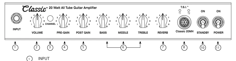
- Input: Standard 1/4" jack for your guitar or effects chain.
- Channel Switch: Selects between 'LEAD' (IN position) and 'RHYTHM' (OUT position) channels.
- Gain & EQ: Includes PRE-GAIN (lead channel input volume), POST-GAIN (lead channel output volume), and passive BASS, MIDDLE, and TREBLE controls.
- Reverb: Adjusts the overall reverb level.
- T.S.I. (Tube Status Indication): LEDs monitor the EL84 power tubes. Green indicates normal operation; red indicates standby, low bias, or a fault condition.
Rear Panel Features
The rear panel contains connectivity and power management options:
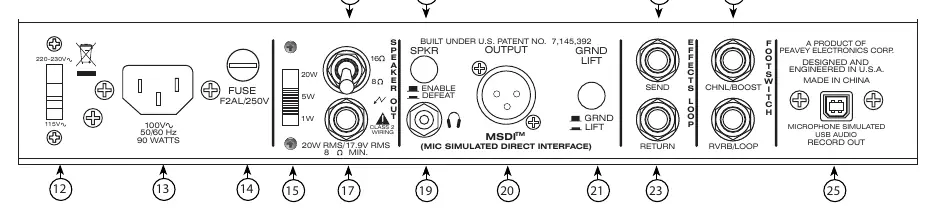
- Power Output Switch: Attenuator allowing selection between 20W (100%), 5W (25%), and 1W (5%) of rated power.
- Impedance Selector: Set to 16Ω or 8Ω to match your speaker cabinet. Minimum load is 8Ω.
- Speaker Output: Connection for external cabinets. Use a proper speaker cable, not a shielded instrument cable.
- Speaker Enable/Defeat: Disconnects the speaker output and redirects to an internal dummy load for silent practice or recording.
- MSDI (Microphone Simulated Direct Interface): Provides a filtered, mic-simulated signal for mixing consoles or recording.
- USB Output: Direct digital recording output derived from the MSDI circuit.
- Effects Loop: Send and Return jacks for external effects processing.
Tube Maintenance and Safety
The amplifier uses 2x EL84 power tubes and 3x 12AX7/ECC83 preamp tubes. If power tubes are replaced, the amplifier must be re-biased. This procedure should be performed by a qualified technician to ensure safety, proper sound quality, and tube longevity. Always ensure proper ventilation by allowing 24 inches of clearance from combustible surfaces and 2 inches of free air space around the unit.
Practical help
Common problems
T.S.I. LEDs are red
Indicates the amp is in Standby, has low bias, or a tube fault. If red during operation, check tubes or consult a technician.
Hum in MSDI output
Engage the Ground Lift switch on the rear panel to eliminate ground loop hum.
No sound from speaker
Check if the Speaker Defeat switch is engaged or if the impedance selector is set incorrectly.
Before use
- Ensure the voltage selector is set to your region's AC line voltage.
- Ensure both POWER and STANDBY switches are in the OFF position.
- Connect the power cord to a grounded outlet.
- Allow 24 inches of clearance from combustible surfaces.
- Ensure 2 inches of free air space for ventilation.
Show more Show less
Specs in practice
- Power Attenuator
- Allows switching output power between 20W, 5W, and 1W to achieve power amp overdrive at lower volumes.
Images and diagrams
- Front panel diagram details input, channel switching, gain, EQ, reverb, and power status.
- Rear panel diagram details power input, impedance selection, speaker outputs, recording interfaces, and effects loop.
Model compatibility
- Minimum speaker load impedance is 8 ohms.
- Use only proper speaker cables for the Speaker Output; do not use shielded instrument cables.

Manual page author
David Miller
Documentation analyst