Electronics / Audio Mixers
Peavey PV 5300 200-Watt 5-Channel Mixer Amplifier User Manual
Quick guide for the Peavey PV 5300 200-Watt 5-Channel Mixer Amplifier. Learn about channel inputs, FLS feedback locating, master EQ, and speaker output connections.
Quick answers from the manual
Quick answer
- The Peavey PV 5300 is a 200-watt, 5-channel powered mixer featuring the FLS Feedback Locating System, digital reverb, and a 5-band graphic EQ. p. 20
Key actions
- Setting up voltage p. 24
- Using FLS to stop feedback p. 22
Problems and fixes
Feedback
Use the FLS system to identify and lower the problematic frequency band.
p. 22Technical specifications
| Parameter | Value | Meaning | Pages |
|---|---|---|---|
| Power Output | 30W RMS (8 ohms), 50W RMS (4 ohms) | Amplifier output power per channel. | p. 26 |
Where to find it in the PDF
- Front Panel Controls p. 21, 22, 23
- Back Panel p. 24
- Specifications p. 26
Table of contents
Manual images
Click an image to enlargeQuick guide from the manual
The Peavey PV 5300 is a 200-watt, 5-channel powered mixer designed for audio reproduction. Before using the unit, it is critical to ensure the correct AC voltage is selected on the back panel. Always maintain at least 6 inches (15.5 cm) of clearance on all sides for proper ventilation. Ensure all equipment is properly grounded to prevent shock or fire hazards.
Product Overview
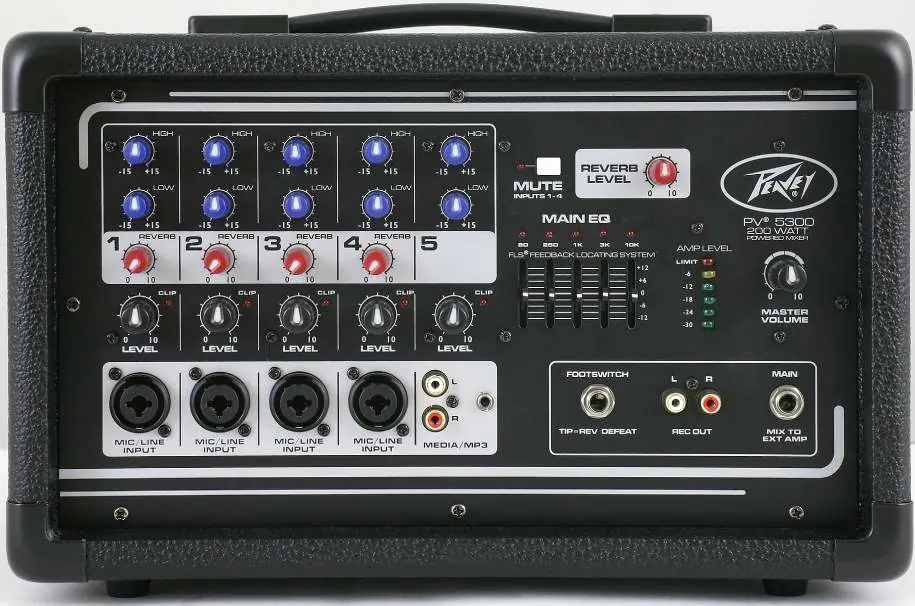
The PV 5300 features four combination XLR and 1/4" inputs with premium mic preamps, a 5-band graphic EQ with FLS (Feedback Locating System), on-board digital reverb, and a master mute switch for channels 1-4.
Channel Inputs
Each channel includes:
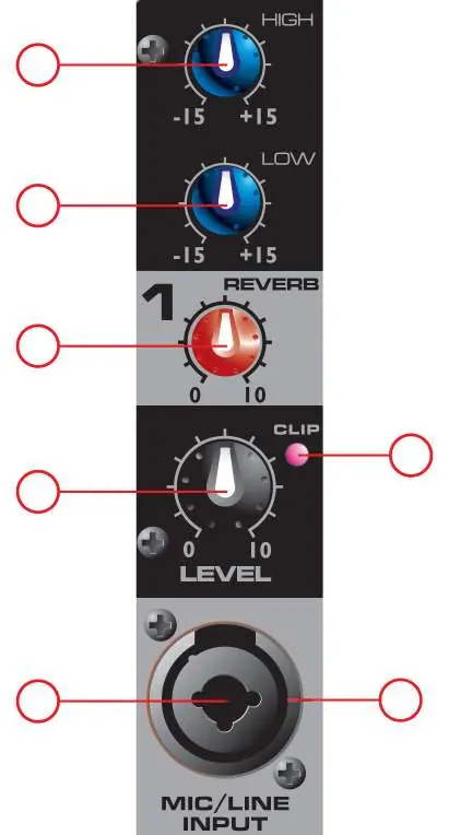
- High/Low Tone Controls: Active shelving EQ (±15 dB).
- Reverb Control: Adjusts the amount of reverb added to the signal.
- Level Control: Adjusts the channel volume sent to the master mix.
- Clip LED: Illuminates when the signal is within 3 dB of clipping.
- Inputs: Combination XLR/1/4" jack for microphones or line-level sources.
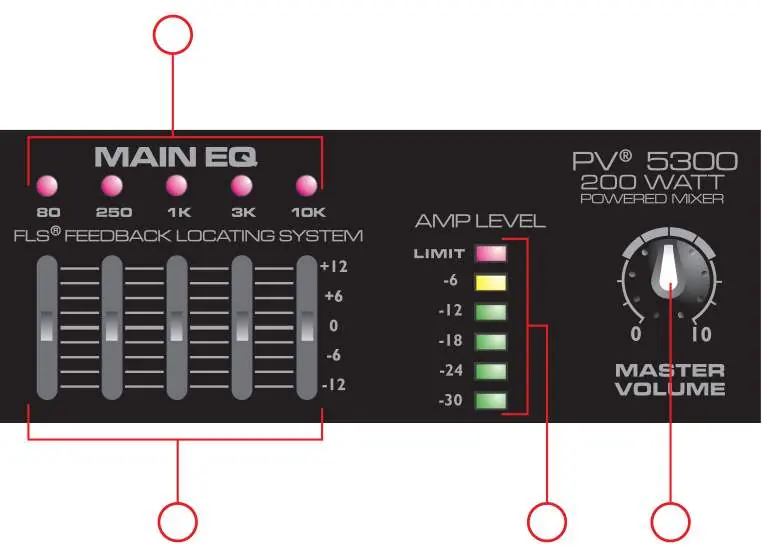
Main EQ and Master Volume
The Main EQ section features the FLS Feedback Locating System. When feedback occurs, the LED corresponding to the problematic frequency band illuminates. Slowly lower that slider until the feedback stops. The Master Volume controls the overall output level. The LED ladder indicates signal levels, with the top LED indicating the activation of the DDT speaker protection circuit.
Back Panel Connections
- Power Switch: Main power control.
- Voltage Selector: Allows switching between 115VAC and 230VAC. Ensure the fuse is changed to the appropriate rating when changing voltage.
- Speaker Outputs: Two 1/4" outputs, each rated at 4 ohms minimum impedance. Use speaker cables, not instrument cables.
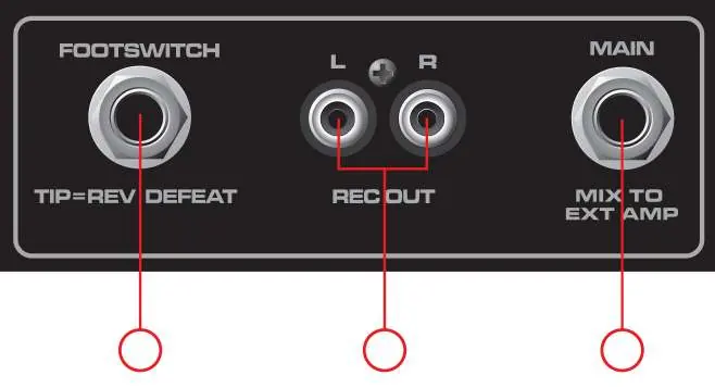
- Main Out: 1/4" jack for connecting an external power amplifier.
- Rec Out: RCA output for recording devices.
Safety and Maintenance
Exposure to high noise levels can cause permanent hearing loss; use hearing protection if operating at high sound pressure levels. Clean the unit only with a dry cloth. Refer all servicing to qualified personnel.
Practical help
Common problems
Feedback (howling/whistling)
Use the FLS Feedback Locating System. Identify the illuminated LED on the graphic EQ and lower that frequency slider until the feedback stops.
Distortion or clipping
Check input levels on each channel. Ensure the speaker impedance is not below the 4-ohm minimum rating.
No sound from channels 1-4
Check if the Mute switch is engaged. The Mute LED will be illuminated if channels 1-4 are muted.
Before use
- Verify the AC voltage selector (115V/230V) matches your local power supply.
- Ensure the fuse rating matches the selected voltage.
- Provide at least 6 inches (15.5 cm) of clearance on all sides for ventilation.
- Ensure all equipment is properly grounded.
- Use speaker cables (not instrument cables) for speaker outputs.
Images and diagrams
- Channel Strip: Shows High/Low EQ, Reverb, Level, and Input jacks.
- Main EQ/Master: Shows the 5-band graphic EQ, FLS LEDs, and Master Volume.
- Back Panel: Shows Power switch, Voltage selector, Fuse, and Speaker outputs.
Model compatibility
- Speaker outputs are rated at 4 ohms minimum impedance.
- Voltage selector must be set correctly before connecting power.
- Do not connect a single device to both Rec Out and Media Input simultaneously to avoid feedback loops.

Manual page author
Emily Carter
User documentation editor
Prepares concise manual descriptions and highlights the most useful setup, operation, and maintenance information for readers.