HVAC / Parts & Accessories
Installation Guide for Danfoss FH-WC 230V Connection Box
Installation guide for the Danfoss FH-WC 230V connection box (088H0016). Includes wiring diagrams, compatibility requirements for FH-WT 230V thermostats, and step-by-step mounting instructions for qualified electricians.
Table of contents
Manual images
Click an image to enlargeQuick guide from the manual
The Danfoss FH-WC 230V connection box is designed for use in heating systems. Important: This product must only be installed by a qualified electrician in accordance with current directive requirements and local regulations. Failure to follow these guidelines may result in improper operation or safety hazards.
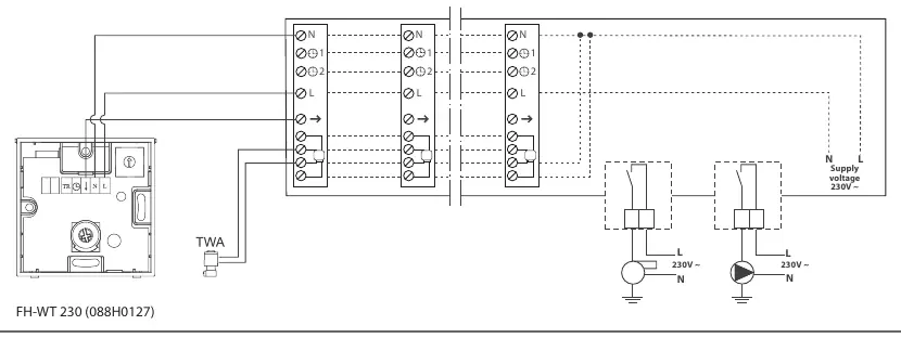
Compatibility: This unit is specifically designed to be used with the Danfoss FH-WT 230V (088H0127) thermostat.
Wiring instructions
The system diagram illustrates the connection of the supply voltage and the thermostat. Ensure the supply voltage is 230V AC. Connect the Live (L) and Neutral (N) wires according to the markings on the terminal block. Ensure all connections are secure and properly insulated.
Connecting multiple actuators
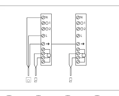
It is possible to connect more than one thermal actuator to a single thermostat using a bridging method. Refer to the bridging diagram to ensure correct wiring of the actuators to the thermostat terminals. Ensure the total load does not exceed the capacity of the thermostat.
Installation steps
Follow these steps for physical installation:
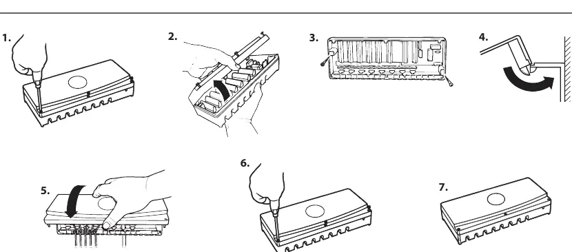
- Remove the cover of the connection box.
- Prepare the wiring and route cables through the designated openings.
- Secure the connection box to the wall or mounting surface.
- Connect the wires to the terminal blocks as indicated in the wiring diagram.
- Replace the cover securely.
Dimensions
The unit measures 313.5 mm in length, 110 mm in height, and 61 mm in depth. Ensure sufficient space is available for installation and cable management.
Manufacturer information
Danfoss A/S
Practical help
Common problems
Incorrect wiring
Ensure L (Live) and N (Neutral) are connected exactly as shown in the system diagram.
Incompatibility
This unit is designed for use with FH-WT 230V (088H0127) thermostats. Do not attempt to use with incompatible models.
Before use
- Verify the power supply is 230V AC.
- Ensure you have the correct compatible thermostat (FH-WT 230V).
- Confirm installation is performed by a qualified electrician.
- Check that all local electrical regulations are met.
Images and diagrams
- System diagram shows L (Live) and N (Neutral) connections for the supply and thermostat.
- Bridging diagram illustrates connecting multiple thermal actuators to a single thermostat.
Model compatibility
- Must be installed with FH-WT 230V (088H0127) thermostats.

Manual page author
David Miller
Documentation analyst
Organizes user manual content into clear summaries, with attention to model details, product context, and everyday usability.