Home / Security
User Manual for Risco RWX73F 2-Way Wireless Multi-Function Contact
Comprehensive user guide for the Risco RWX73F 2-Way Wireless Multi-Function Contact. Includes installation instructions, RF communication setup, input wiring diagrams, parameter configuration, and technical specifications.
Quick answers from the manual
Quick answer
- The RWX73F is a 2-way wireless multi-function transmitter with magnetic contact and two additional inputs. It is registered to the system via RF allocation using DIP switch 1. p. 1
Key actions
- Registering the transmitter p. 1
- Mounting the device p. 1
First start
- Insert battery, set DIP switch 1 to OFF for Channel 1, and press the front tamper switch for 3 seconds to register. p. 1
Show 4 more answers Show less
Problems and fixes
Signal not detected
Reposition the transmitter and try again.
p. 1Maintenance and reset
- Test the product at least once a week. p. 1
Technical specifications
| Parameter | Value | Meaning | Pages |
|---|---|---|---|
| Battery | CR123 3V Lithium | Power source | p. 1 |
| Frequency | 868.65 MHz / 433.92 MHz | Operating frequency | p. 1 |
Where to find it in the PDF
- Installation and Specifications p. 1
Table of contents
Manual images
Click an image to enlargeQuick Guide
The Risco RWX73F is a 2-way wireless multi-function transmitter designed for security systems. It features two channels: one for magnetic contact and one for universal inputs (or shutter). Key setup steps include registering the device to the receiver via RF allocation, mounting the transmitter and magnet, and configuring parameters via the control panel.
Installation
Transmitter and Magnet Mounting:
- Mount the transmitter on the non-moving part (door/window frame) and the magnet on the moving part.
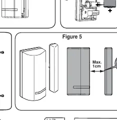
- Ensure the alignment marks on the magnet case and transmitter case are aligned.
- For wood or alloy, the maximum operating distance is 10 mm. For metal/ferromagnetic materials, the maximum distance is 5 mm.
- Use spacers if necessary to ensure proper alignment between the transmitter and the mounting surface.
- Secure the back bracket using the provided mounting screws and back tamper screw.
Communication Setup
The transmitter must be registered to the system receiver:
- Remove the front cover and insert the battery (check polarity).
- Set the main unit to Learn mode on the control panel.
- For Channel 1: Set DIP switch 1 to OFF. Press the front tamper switch for at least 3 seconds until the panel recognizes the device.
- For Channel 2: Set DIP switch 1 to ON. Repeat the registration process.
Input Wiring
The device supports different input terminations. For DEOL (Double End of Line) termination, connect two 10K Ohm resistors as specified in the wiring diagrams provided in the manual. Ensure the wiring matches the intended configuration (Normally Closed or Normally Open).
Parameter Configuration
Parameters can be defined for each channel from the control panel, including:
- Supervision: Enable/Disable.
- LED Enable: Enable/Disable.
- Magnet: Enable/Disable (Channel 1 only).
- Alarm Hold: On/Off.
- Termination: Select between NO, NC, or DEOL.
- Response: 10ms or 500ms.
- Anti-sabotage: Enable/Disable (Channel 1 only).
Technical Specifications
- Battery: CR123 3V Lithium Battery (3 years typical life).
- Frequency: 868.65 MHz (RWX73F86800A) or 433.92 MHz (RWX73F43300A).
- Range: Up to 300 m (1,000 ft) line of sight.
- Operating Temperature: 0°C to 40°C (32°F to 104°F).
Practical help
Common problems
Alarm signal not received by the panel
Reposition the transmitter to a location with better communication quality and try again.
Low battery indication
Replace the battery with a CR123 3V Lithium Battery. Dispose of used batteries according to local regulations.
Tamper alarm triggered
Ensure the front cover is properly closed and the back bracket is securely mounted.
Before use
- Remove battery insulation material
- Verify battery polarity
- Set DIP switch 1 to OFF for Channel 1 registration
- Set DIP switch 1 to ON for Channel 2 registration
- Check alignment marks on magnet and transmitter
- Verify mounting distance (10mm for wood/alloy, 5mm for metal)
Show more Show less
Specs in practice
- Dead Time (HOLD ON)
- A 2.5-minute period where the transmitter does not send new alarm signals to conserve battery.
Images and diagrams
- Figure 1: Back bracket mounting.
- Figure 2: Battery insertion and DIP switch location.
- Figure 5: Alignment marks for magnet and transmitter.
- Figure 6: Optional spacer mounting.
Model compatibility
- Compatible with RISCO Group 2-Way wireless systems.

Manual page author
David Miller
Documentation analyst