Toys / RC Models & Drones
User Manual for Robbe ASW 15B RC Glider
Quick guide for the Robbe ASW 15B RC Glider. Includes assembly steps for servos, motor, and tailplane, flight settings, control throws, and safety instructions.
Table of contents
Manual images
Click an image to enlargeQuick guide from the manual
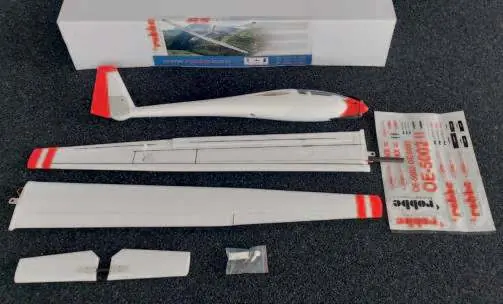
The Robbe ASW 15B is a semi-scale RC glider designed for both intermediate and experienced pilots. This manual covers the assembly and operation of the ARF (Almost Ready to Fly) and PNP (Plug and Play) versions. Always perform a functional test of the drive train and remote control before the first flight.
General Safety Information
- Batteries: Never charge or discharge on flammable surfaces. Do not leave unattended. Keep away from water and fire.
- Operation: Maintain a safe distance from spectators. Do not fly near power lines, residential areas, or public roads.
- Rotating Parts: Keep clear of the propeller when the battery is connected.
- Temperature: Avoid leaving the model in direct sunlight or hot vehicles to prevent deformation.
Flight Instructions
- Choose a day with minimal wind for the first flight.
- Perform a functional test of the drive train and remote control.
- Ensure all components (wing, tail, motor, linkages) are firmly fastened.
- The start should be against the wind.
- Initiate landing with sufficient speed and avoid tight turns near the ground.
Assembly Instructions
Aileron Servo Installation
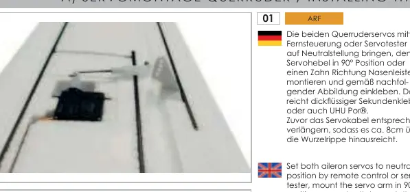
- Set servos to neutral using a remote or servo tester.
- Mount the servo arm at 90° or one tooth towards the leading edge.
- Glue the servo and rudder lever in place using thick super glue or UHU Por.
- Extend the servo cable to reach 8cm beyond the root rib.
Rudder/Elevator Servo Installation
- Remove the rear plastic bracket for the fuselage servos.
- Place servos in the provided holders.
- Thread the extended servo cable through the fuselage tube.
- Connect the elevator linkage to the bellcrank and adjust the clevis for neutral position.
Motor Installation
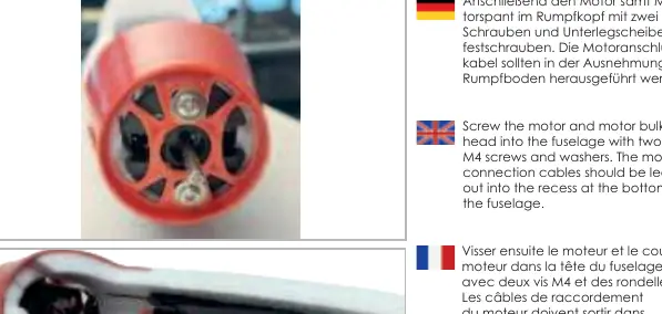
- Screw the brushless motor to the motor bulkhead.
- Ensure motor connection cables are at 90° to the recesses on the bulkhead.
- Secure the motor in the fuselage with M4 screws.
- Check rotation direction before mounting the folding propeller.
Tailplane and Model Assembly

- The elevator is fixed using a carbon 4-sided tube and a snap lock.
- Slide the elevator into the fuselage holder until the leading edge aligns with the molding.
- For wing assembly, insert the carbon connector, plug in servo cables, and secure the wing with the retainer, turning it 90° to lock.
Control Throws and Center of Gravity
The center of gravity (C.G.) is 50-60mm from the leading edge, measured at the root rib. Recommended control throws:
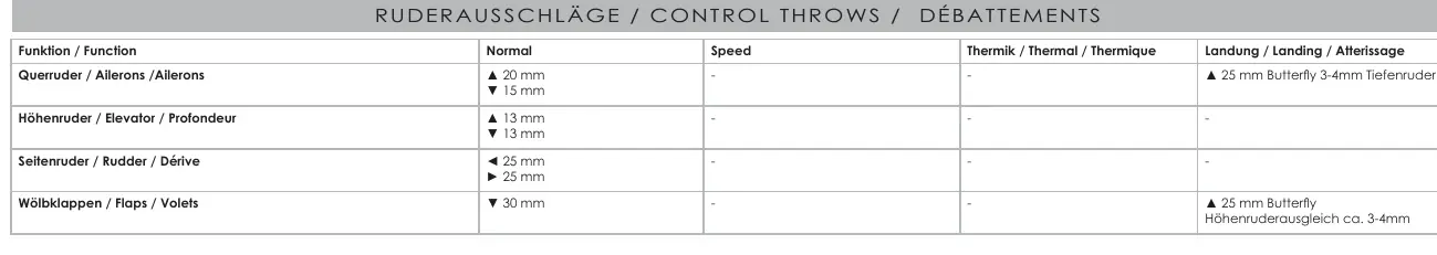
- Aileron: 20mm up, 15mm down.
- Elevator: 13mm in both directions.
- Rudder: 25mm in both directions.
- Flaps (Thermal): 5-10mm down.
- Flaps (Landing/Butterfly): 30mm down, with 25mm aileron up and 3-4mm elevator compensation.
Technical Data
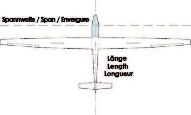
- Span: 2270 mm
- Length: 970 mm
- Flying weight: 1150 g
Practical help
Common problems
Motor vibration
Rebalance the propellers.
Bubble formation in covering foils
Use a foil iron or hairdryer to smooth the surface.
Servo arm movement
Adjust neutral position by one tooth if needed for specific deflection requirements.
Before use
- Check wing symmetry and tail unit alignment.
- Perform a functional test of the drive train and remote control.
- Ensure all components (wing, tail, motor) are firmly fastened.
- Verify the center of gravity (50-60mm from leading edge).
- Check battery position and secure with Velcro straps.
Specs in practice
- Flying weight
- 1150 g
Images and diagrams
- Assembly steps for servos, motor, and tailplane are provided in sections A through E.
- Control throws table provides specific settings for Normal, Speed, Thermal, and Landing modes.
Model compatibility
- Servo mount dimensions: 23mm x 11.7mm x 20.8mm.
- Recommended battery: 3S LiPo 2500mAh.

Manual page author
Emily Carter
User documentation editor
Prepares concise manual descriptions and highlights the most useful setup, operation, and maintenance information for readers.