Toys / RC Models & Drones
User Manual for FMS 1500MM P-47 Razorback RC Plane
Quick guide for the FMS 1500MM P-47 Razorback RC plane. Includes assembly instructions, battery installation, radio setup, center of gravity (CG) balancing, and troubleshooting tips.
Table of contents
Manual images
Click an image to enlargeQuick guide from the manual
This manual provides essential instructions for the assembly, setup, and operation of the FMS 1500MM P-47 Razorback. Before operating, ensure you have read all safety precautions, particularly regarding Li-Po battery handling. Always perform a ground range check before your first flight and ensure all screws are tightened.
Safety Precautions
- Age Recommendation: Not for children under 14 years.
- Li-Po Battery Safety: Always use a Li-Po compatible charger. Never charge unattended. Store batteries at room temperature in a dry area. Never discharge below 3V per cell.
- Operational Safety: Never operate near people, cars, or in populated areas. Always maintain a safe distance.
Assembly Instructions
Horizontal Tail Installation
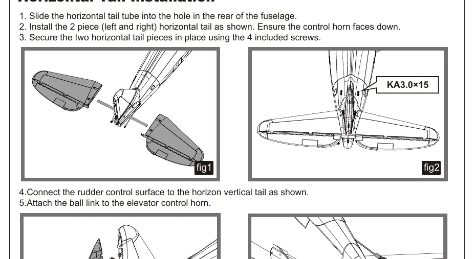
- Slide the horizontal tail tube into the hole in the rear of the fuselage.
- Install the left and right horizontal tail pieces, ensuring the control horn faces down.
- Secure the pieces using the 4 included screws.
- Connect the rudder control surface and attach the ball link to the elevator control horn.
Main Wing Installation
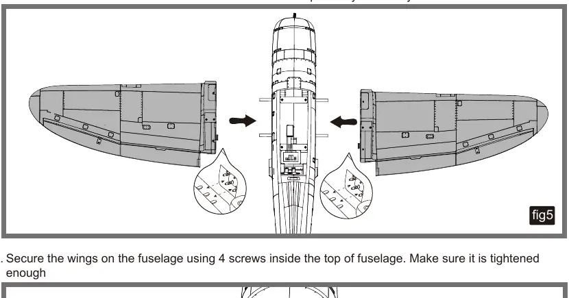
- Slide the two tubes into the fuselage.
- Install both wings over the wing tubes and into the wing slots. Ensure connectors are attached firmly.
- Secure the wings using the 4 screws inside the top of the fuselage.
Accessories Installation
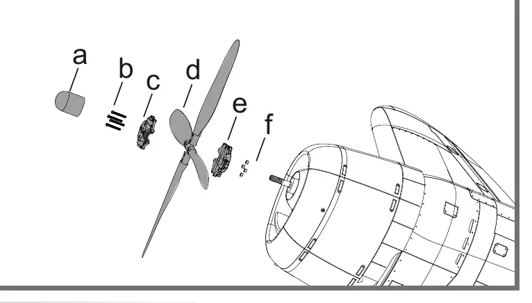
Install the rocket tubes, drop tank, bombs, machine guns, and antenna using foam-safe CA adhesive as indicated in the diagrams.
Battery and Radio Installation
Apply hook tape to the battery cable end. Slide the battery into the hatch with the power cable facing the rear. Ensure the battery position is adjusted to achieve the correct Center of Gravity (CG).
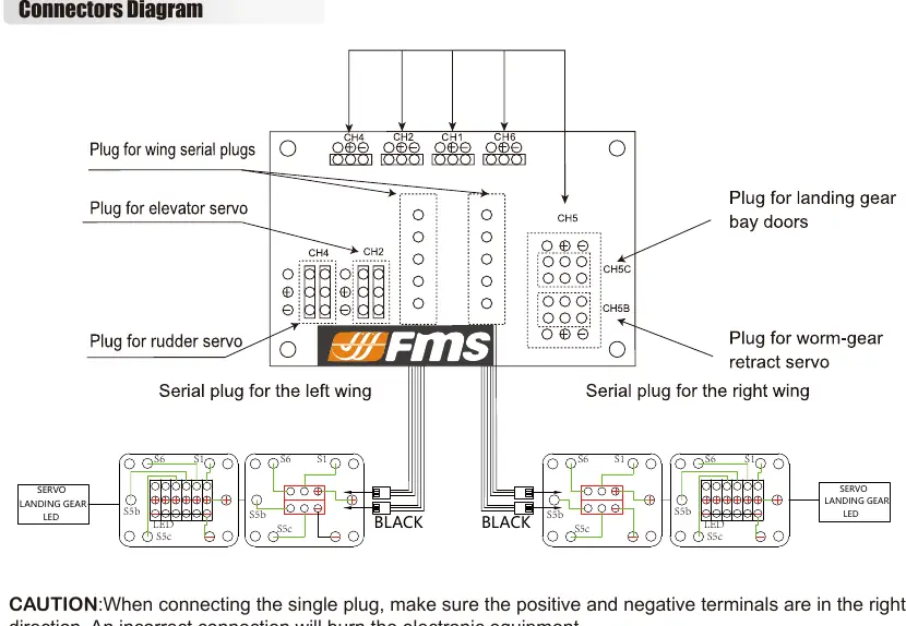
Connectors Diagram
The fuselage features a central port for wing connections. Ensure positive and negative terminals are connected in the correct direction to avoid damaging electronic equipment.
Setup and Calibration
ESC and Transmitter
- ESC Safe Start: The motor will not start until the throttle stick is moved to the low or off position.
- Motor Rotation: Should be clockwise when viewed from the rear. If incorrect, reverse two of the three motor wires.
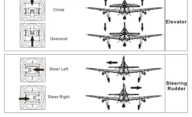
- Control Throws: Set dual rates as follows: Elevator: 18mm (High) / 14mm (Low); Aileron: 16mm (High) / 12mm (Low); Rudder: 30mm (High) / 22mm (Low).
Center of Gravity (CG)
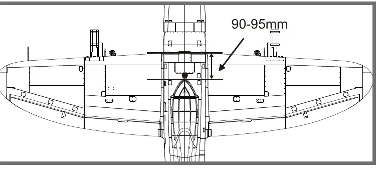
The recommended CG is 90-95mm forward from the leading edge of the main wing. Balance the plane with the battery installed, supporting it at the marks on the bottom of the main wing.
Flying Your Model
- Takeoff: Apply power slowly to keep the model straight.
- Landing: Land when you hear the motor pulsing (LVC) or notice a power reduction. Use 1/4-1/3 throttle to maintain energy for the flare.
- Flight Time: Set a conservative timer (e.g., 4 minutes) for the first flight to avoid dead-stick landings.
Maintenance
Repairs to the foam should be made using foam-safe adhesives such as hot glue, foam-safe CA, or 5-minute epoxy. Regularly check that all screws are tightened and the spinner is secure.
Manufacturer information
FMS Model
Practical help
Common problems
Aircraft will not respond to throttle
Ensure ESC is armed, throttle stick is at low/off position, or check if the throttle channel is reversed on the transmitter.
Extra propeller noise or vibration
Check for damaged spinner/propeller, loose parts, or ensure the propeller is not installed backwards.
Reduced flight time or underpowered
Check battery charge, battery health, or ensure the propeller is installed correctly.
Control surface does not move
Check for damaged control horn, linkage, servo, or loose wiring connections.
Before use
- Charge the Li-Po battery fully.
- Perform a ground range check with an assistant.
- Ensure all servo wires are securely connected.
- Verify control surfaces move in the correct direction.
- Check that all screws are tightened.
- Verify Center of Gravity (CG) is 90-95mm from the leading edge.
Specs in practice
- Flying Weight
- Around 3700g
Images and diagrams
- Connectors Diagram (Page 9): Shows how to connect wing serial plugs, elevator servo, rudder servo, and landing gear to the fuselage port.
- Control Throws (Page 11): Illustrates high and low rate settings for elevator, aileron, and rudder.
- Center of Gravity (Page 13): Shows the correct balance point 90-95mm from the leading edge.
Model compatibility
- Recommended battery: 22.2V 5000mAh 35C Li-Po.
- Use foam-safe adhesives (e.g., foam-safe CA, hot glue, 5min epoxy) for repairs.

Manual page author
David Miller
Documentation analyst
Organizes user manual content into clear summaries, with attention to model details, product context, and everyday usability.