Tools / Power Tools
Ryobi 18V Brushless Hammer Drill User Manual (PBLHM101)
Quick guide for the Ryobi 18V Brushless Hammer Drill (PBLHM101). Includes assembly, operation, torque adjustment, drilling modes, and troubleshooting.
Table of contents
Manual images
Click an image to enlargeQuick guide from the manual
This manual provides instructions for the Ryobi 18V Brushless Hammer Drill (PBLHM101). It covers safety, assembly, operation, and maintenance. Always read the full manual for complete safety information.
Safety Warnings
- Eye Protection: Always wear eye protection with side shields marked to comply with ANSI Z87.1.
- Dust Protection: Wear a face or dust mask if the operation is dusty.
- Hearing Protection: Wear ear protectors during extended periods of operation or when impact drilling.
- Battery Safety: Do not use damaged or modified batteries. Keep battery packs away from metal objects to prevent short circuits.
Assembly
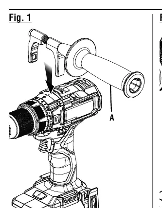
Installing the Auxiliary Handle
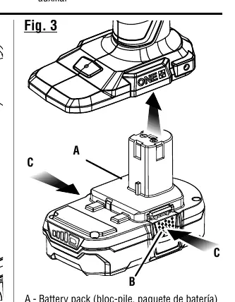
- Remove the battery pack.
- Turn the handle grip counterclockwise to loosen it.
- Place the hooks over the mounting ribs behind the torque adjustment ring.
- Turn the handle grip clockwise to tighten.
Installing/Removing Bits
- Lock the switch trigger.
- Open the chuck jaws until the opening is slightly larger than the bit size.
- Insert the drill bit straight into the chuck jaws.
- Tighten the chuck sleeve securely.
Operation
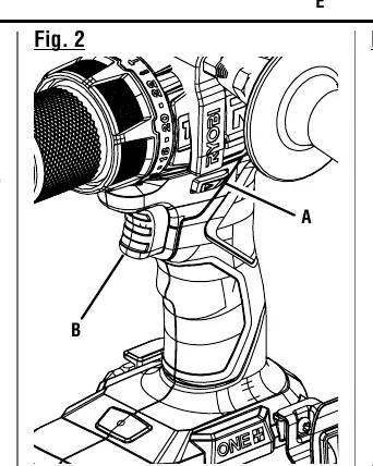
Variable Speed Switch Trigger
The trigger delivers higher speed with increased pressure and lower speed with decreased pressure. To turn the tool ON, depress the trigger. To turn it OFF, release the trigger.
Direction of Rotation Selector
Set the selector to the left for forward drilling, to the right for reverse, and to the center (OFF) to lock the trigger when not in use.
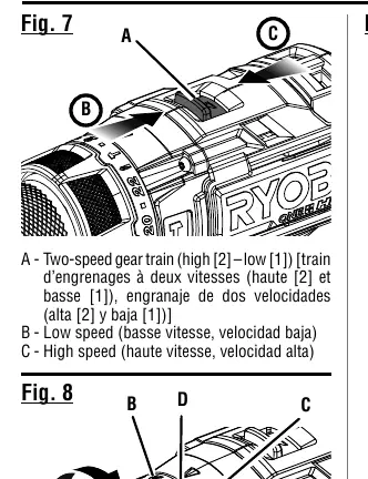
Two-Speed Gear Train
- Low Speed (1): Use for applications requiring higher power and torque (e.g., driving screws, drilling in metal).
- High Speed (2): Use for fast drilling or driving applications (e.g., wood, masonry, hammer drilling).
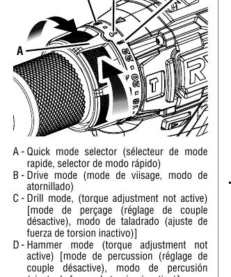
Quick Mode Selector
Allows switching between modes:
- Drive Mode: For driving screws.
- Drill Mode: For drilling and heavy-duty applications.
- Hammer Mode: For drilling into masonry and concrete.
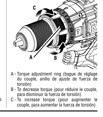
Adjusting Torque
Rotate the torque adjustment ring to increase or decrease torque. Higher settings provide more torque for driving larger screws.
Troubleshooting
The drill features an LED light that indicates tool status:
- Solid Light: Normal operation.
- 3 Flashes: Low battery (replace/recharge).
- 6 Flashes: Excessive force (wait 5 seconds).
- 9 Flashes: Over temperature (let tool cool).
Manufacturer information
Ryobi
Practical help
Common problems
Drill overheats during low-speed usage
Cool the drill by running it without a load at full speed.
Bit slips in chuck
Ensure the bit is inserted straight and the chuck is tightened properly without using a wrench.
LED light flashes 3 times
Battery is low; replace or recharge the battery pack.
LED light flashes 6 times
Excessive force detected; wait 5 seconds before resuming.
LED light flashes 9 times
Tool is over temperature; let the tool cool off.
Before use
- Check for damaged or missing parts.
- Ensure the battery pack is fully charged.
- Install the auxiliary handle if required for the task.
- Select the correct speed (1/Low or 2/High).
- Select the correct mode (Drive, Drill, or Hammer).
- Verify the rotation selector is set to forward or reverse.
Specs in practice
- No Load Speed
- 0–500/0–2,100 RPM (rotational speed without load).
- Hammer Speed
- 0–5,400/0–31,000 BPM (blows per minute).
Images and diagrams
- Fig 1: Auxiliary handle installation.
- Fig 2: Variable speed trigger and rotation selector.
- Fig 3: Battery pack installation.
- Fig 4-5: Bit installation and chuck operation.
- Fig 7: Two-speed gear train switch.
Model compatibility
- Use only with batteries and chargers listed in the tool/appliance/battery pack/charger correlation supplement 987000-432.

Manual page author
Michael Turner
Technical manual editor
Reviews PDF manuals for structure, safety notes, and practical product details so readers can find the right information quickly.