Plumbing / Toilets Urinals
Installation and Operating Manual for Sanela SLW 01NK/01NKX Automatic Toilet Flushing Unit
Quick guide for the Sanela SLW 01NK and SLW 01NKX automatic toilet flushing units. Includes installation steps, wiring diagrams, parameter settings, and maintenance tips.
Table of contents
Manual images
Click an image to enlargeQuick Guide
The Sanela SLW 01NK and SLW 01NKX are automatic toilet flushing units designed for pressured water systems. The system operates on 24V DC and requires a constant power supply. Key operational parameters include a water pressure range of 0.15 to 0.6 MPa and a sieve dimension of 90 µm or less.
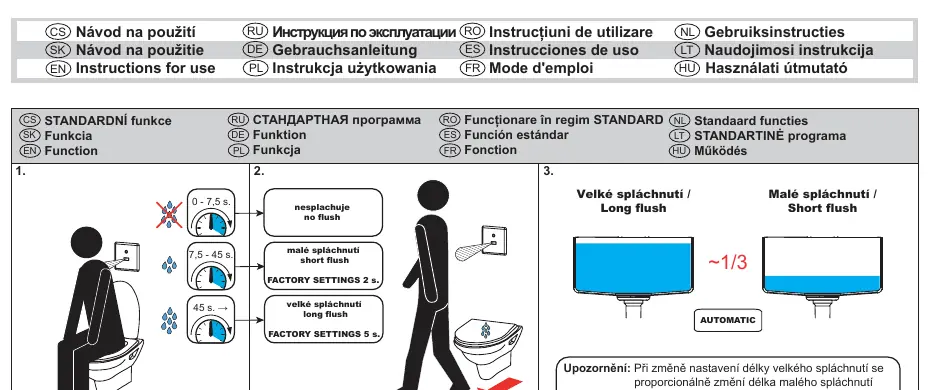
Important: For proper function, the unit must be kept under constant voltage. Do not connect the power supply unit behind a light switch or motion sensor.
Installation
Installation should be performed by qualified personnel. Ensure the water supply is turned off before beginning.
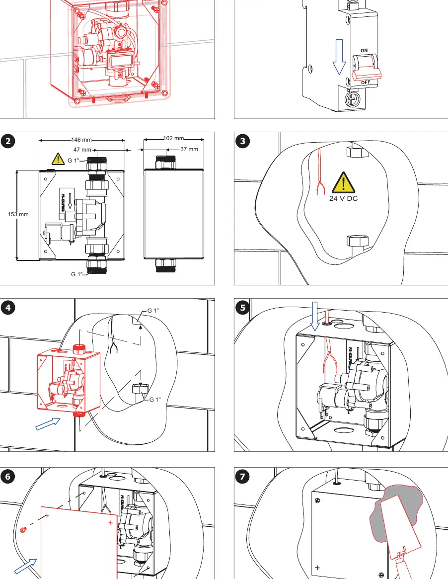
- Ensure the installation box is properly mounted in the wall.
- Connect the water supply (G 1" connection).
- Perform the wiring connection as detailed in the wiring diagram.
- Secure the front cover plate.
- Once installed, the system performs an automatic adjustment (approx. 10 seconds).
Wiring and Power
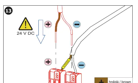
The unit requires a 24V DC power supply. Connect the brown wire to the positive (+) terminal and the white wire to the negative (-) terminal. Ensure the power source is constant and not interrupted by external switches.
Settings and Adjustments
The flushing parameters can be adjusted using the Sanela SLD 03 remote control. The unit features automatic flushing and a manual flushing option.
Water Flow Adjustment
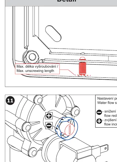
If the water flow needs adjustment, locate the flow control screw on the valve (see Detail 11 in the manual):
- Flow reduction: Turn the screw to decrease flow.
- Flow increase: Turn the screw to increase flow.
Maintenance
Regular maintenance is recommended to ensure long-term reliability. Check the sieve for debris periodically. If the unit is not functioning, verify the power supply and water pressure first. For advanced configuration, use the Sanela Control application available on Google Play and the App Store.
Technical Data
- Power Supply: 24V DC
- Water Pressure: 0.15 - 0.6 MPa
- Sieve Dimension: ≤ 90 µm
- Sensor Range: 0.3 - 0.7 m
- Flush Settings: Adjustable via remote control
Manufacturer information
SANELA spol. s r. o.
Practical help
Common problems
Unit does not flush
Verify the power supply is 24V DC and constant. Ensure it is not connected behind a light switch.
Water flow is too high or too low
Adjust the flow control screw on the valve (turn clockwise to reduce, counter-clockwise to increase).
Sensor not detecting presence
Check the sensor range (0.3 - 0.7 m) and ensure the sensor area is clean.
Before use
- Ensure water pressure is between 0.15 and 0.6 MPa.
- Verify power supply is 24V DC and constant.
- Check that the installation box is properly mounted.
- Ensure the sieve is clean (dimension ≤ 90 µm).
- Confirm wiring polarity (Brown: +, White: -).
Specs in practice
- 0.15 - 0.6 MPa
- Operating water pressure range.
Images and diagrams
- Page 3 illustrates the step-by-step installation of the flushing unit into the wall box.
- Page 4 shows the wiring connection (brown/white wires) and the location of the water flow adjustment screw.
Model compatibility
- Requires SLD 03 remote control for advanced parameter settings.
- Compatible with Sanela power supplies (SLZ 01Y, SLZ 01Z, SLZ 04Y, SLZ 04Z, SLZ 04X).

Manual page author
Michael Turner
Technical manual editor
Reviews PDF manuals for structure, safety notes, and practical product details so readers can find the right information quickly.