Industrial / Access Control
SDC 1490AI Failsafe Extra Narrow Concealed Mortise Bolt Lock
Installation and wiring guide for the SDC 1490AI Failsafe Extra Narrow Concealed Mortise Bolt Lock. Includes mounting instructions, solenoid voltage configuration, wiring diagrams, and troubleshooting.
Table of contents
Manual images
Click an image to enlargeQuick Guide from the Manual
The SDC 1490AI is a failsafe, extra narrow concealed mortise bolt lock designed for metal doors and frames. Installation involves mortising a cutout, attaching wiring, and securing the lock with mounting tabs. The unit features an adjustable Auto Relock Switch (ARS) to compensate for door gaps. For optimal performance and heat reduction, the use of the included PR-1000 Power Regulator is recommended.
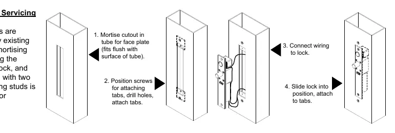
Installation Instructions
Overhead Installation (Horizontal):
- Examine the top rail of the door to locate the strike plate position. Mark the door for the end of the strike closest to the lock stile and make a corresponding mark on the header.
- Locate the center line of the door thickness on the header. Attach the adhesive cutout template, center punch the tab-mounting screw locations, and counter-sink for #10 screws.
- Saw or rout out the cutout area.
- Attach mounting tabs inside.
- Connect power supply and access control leads to the lock leads. Insert wiring into the header cavity carefully.
- Insert the lock (bolt end nearest the lock stile) and secure with #10-32 machine screws.
- Using the strike plate as a template, mark and drill screw holes. Mortise as required and attach the strike.
Sidejamb Installation (Vertical):
- Examine the lock stile jamb for the point nearest the center of the door height. Mark the door stile horizontal for the top end of the strike plate and make a corresponding mark on the jamb.
- Locate the center line of the door thickness on the jamb and attach the adhesive cutout template.
- Center punch the tab mounting screw locations, counter-sink for #10 screws, and saw or rout the frame cutout.
- Attach mounting tabs inside and proceed with wiring and lock insertion as described in the overhead installation steps. The bolt must be at the top end of the cutout.
Auto Relock Switch (ARS) Adjustment
The ARS is factory-set for a 1/8 inch clearance between the top of the door and the transom bar or head jamb. If there is a wider gap, you can compensate by:
- Loosening the lock nut.
- Turning the switch assembly clockwise until the proper adjustment is reached.
- Tightening the lock nut securely.
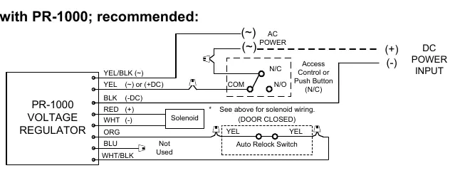
Wiring and Power Configuration
The solenoid is rated for continuous duty, but the PR-1000 Power Regulator is recommended to reduce power consumption and heat. The unit supports both 12VDC and 24VDC configurations. Ensure the power supply matches the solenoid voltage requirements. Detailed wiring diagrams for configurations with and without the PR-1000 are provided in the manual.
Troubleshooting
- Bolt does not project: Check voltage and alignment of the strike.
- Bolt projects but chatters: Voltage is too low.
- Bolt will not retract: Strike is mis-aligned.
Technical Data
- Face Plate: 8" x 1-1/4" x 1/8"
- Strike: 4" x 1-1/2" x 1/8"
- Bolt: 5/8" diameter, solid stainless steel
- Bolt Throw: 1/2"
- Power Requirements: 12VDC @ .9 Amp (Max) or 24VDC @ .45 Amp (Max)
Practical help
Common problems
Bolt does not project
Check voltage and alignment of the strike plate.
Bolt projects but chatters
Voltage is too low; ensure proper power supply.
Bolt will not retract
Strike is mis-aligned; adjust position.
Before use
- Verify the door is a metal door/frame type.
- Ensure the power supply matches the solenoid voltage (12VDC or 24VDC).
- Confirm the PR-1000 Power Regulator is available for installation.
- Check that the strike plate alignment is correct.
- Ensure the Auto Relock Switch (ARS) is adjusted for the specific door gap.
Specs in practice
- 24VDC @ .45 Amp
- Power requirement for 24V configuration (Continuous Duty).
- Bolt Throw: 1/2"
- The distance the bolt extends to lock the door.
Images and diagrams
- Wiring diagrams illustrate connections for 12VDC and 24VDC, with and without the PR-1000 regulator.
- Installation diagrams show the mortise cutout dimensions for both door and frame preparation.
- ARS adjustment diagram shows how to loosen the nut and turn the assembly for wider door gaps.
Model compatibility
- Designed for metal doors and frames.
- PR-1000 module is required when mounted in the frame for heat reduction.
- Optional BPS (Bolt Position Sensor) and DPS (Door Position Switch) are available.

Manual page author
Michael Turner
Technical manual editor
Reviews PDF manuals for structure, safety notes, and practical product details so readers can find the right information quickly.