Industrial / Access Control
SDC 1561S Surface Electromagnetic Shear Lock Installation Manual
Comprehensive installation and maintenance guide for the SDC 1561S HiSHEAR Surface Magnetic Lock. Includes detailed mounting instructions for right and left-hand reverse doors, wiring diagrams, timer adjustments, and troubleshooting tips.
Table of contents
Manual images
Click an image to enlargeImportant Information
The SDC 1561S HiSHEAR Surface Magnetic Lock is designed for right-hand-reverse or left-hand-reverse doors. It provides a maximum holding force of 2000 lbs. Proper alignment is critical for this device; it is less forgiving than standard electric bolt locks. Ensure all door latching problems are corrected before installation.
Installation Preparation
Before beginning the installation, ensure the following conditions are met:
- The clearance between the door top and frame header must be 1/8 inch.
- Adjust the door and door closer so the door settles immediately and is fully closed at rest.
- For double-acting doors, ensure they are fully closed and at rest in the dead center of the frame.
- Verify that the labels on the L-brackets of the Magnet Lock and Armature are facing the leading edge of the door.
Mounting the Magnet Assembly
The magnet assembly is mounted to the frame header. Follow these steps:
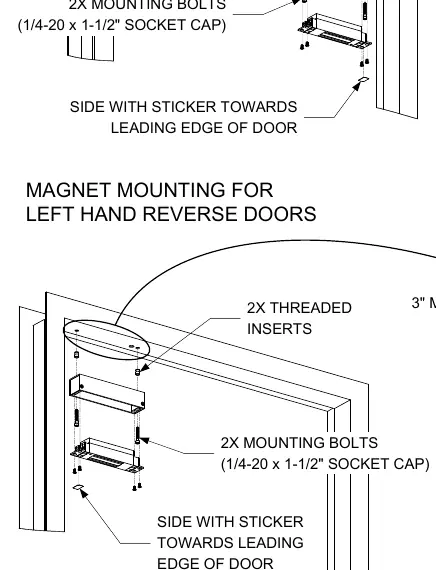
- Prep the frame header according to the dimensions provided in the manual for your specific door handing (Right-Hand-Reverse or Left-Hand-Reverse).
- Mount the Magnet Assembly to the frame header using the provided threaded inserts and mounting bolts.
Mounting the Armature Assembly
The armature is mounted to the door. Follow these steps:
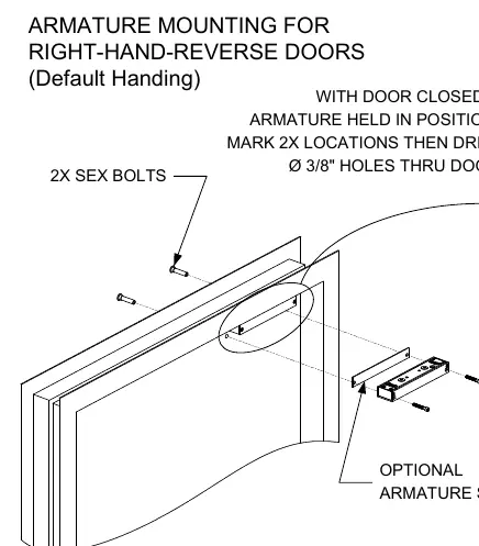
- Prep the door according to the dimensions provided in the manual.
- If installing on a left-hand-reverse door, remove the armature from its housing, rotate it 180 degrees, and reinstall it in the housing. The brass screw on top of the armature must face the leading edge of the door.
- Mount the Armature Assembly to the door using the provided sex bolts and mounting bolts.
- Ensure there is a 1/8 inch minimum gap between the armature and the magnet face.
Wiring and Timer Adjustment
The unit features an integrated auto relock delay timer, adjustable from 1 to 6 seconds (factory set to approximately 3 seconds).
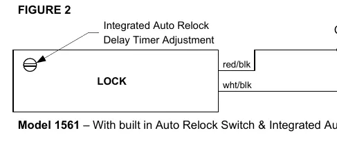
- Wiring: Connect to a properly fused 12VDC or 24VDC power source with the power off.
- Timer Adjustment: Use a small flat-blade screwdriver through the small hole in the face of the magnet. Turn clockwise to increase the time and counter-clockwise to decrease the time.
Troubleshooting and Alignment
If positive locking cannot be attained due to misalignment, refer to the shear tab installation diagrams. The armature shear stops should be centered between each pair of magnet lock shear stops. If the clearance between the shear stops is sufficient, open and close the door several times to verify positive locking.
Maintenance
The electromagnet and armature surfaces must be kept clean. Any damage such as paint, burrs, dirt, or rust can reduce holding power.
- Do not touch the lock face with your hands.
- Clean the lock face using a soft, clean, dry cloth or an abrasive cloth like Scotch-Brite by 3M. Do not use sandpaper.
- Apply a rust inhibitor (such as Starret M1 or LPS3) to the lock face and armature face if the plating becomes damaged.
Practical help
Common problems
Door not locking positively
Check alignment of the armature shear stops. Ensure clearance between armature and lock is not greater than 1/8 inch.
Surface damage or rust on lock face
Clean with a soft cloth or Scotch-Brite (no sandpaper) and apply a rust inhibitor like Starret M1 or LPS3.
Door latching issues
Door latching problems must be corrected prior to installing the shear lock.
Before use
- Verify door latching problems are corrected.
- Ensure 1/8 inch clearance between door top and frame header.
- Check that the door is fully closed and at rest.
- Verify power source is fused.
- Confirm door handing (Right-Hand-Reverse or Left-Hand-Reverse) for correct mounting.
Specs in practice
- Holding Force
- 2000 lbs maximum.
- Relock Delay
- Adjustable 1-6 seconds via potentiometer.
- Power Consumption (12VDC)
- 650mA.
- Power Consumption (24VDC)
- 350mA.
Images and diagrams
- Figure 2 illustrates the wiring connections and the location of the auto relock delay timer potentiometer.
- Figure 3 shows the armature shear tab installation and alignment for normal and warped doors.
Model compatibility
- Designed for Right-Hand-Reverse or Left-Hand-Reverse doors only.
- Requires a high-quality door closer for proper operation.

Manual page author
Emily Carter
User documentation editor
Prepares concise manual descriptions and highlights the most useful setup, operation, and maintenance information for readers.