Industrial / Access Control
Installation Guide for SDC 1490A Bolt Lock
Comprehensive installation and wiring guide for the SDC 1490A Space Saver bolt lock. Includes step-by-step mounting instructions for overhead and sidejamb configurations, wiring diagrams with PR-1000 regulator, voltage settings, and...
Table of contents
Quick Installation Overview
The SDC 1490A Space Saver lock is designed for installation in existing entrances. The general installation process involves four main steps:
- Mortise cutout: Prepare the cutout in the tube for the face plate so it fits flush.
- Attach tabs: Position screws for attaching tabs, drill holes, and secure the tabs.
- Connect wiring: Connect the power supply and access control leads to the lock.
- Slide lock: Insert the lock into position and attach it to the tabs.
Installation
The lock can be installed in two configurations:
Overhead Installation (Horizontal)
- Examine the top rail of the door to locate the strike plate.
- Mark the door for the end of the strike closest to the lock stile and make a corresponding mark on the header.
- Attach the adhesive cutout template to the header, aligning it with your marks.
- Center punch the tab-mounting screw locations and countersink for #10 screws.
- Saw or rout out the cutout area.
- Insert the lock with the bolt end nearest the lock stile.
Sidejamb Installation (Vertical)
- Examine the lock stile jamb for the center of the door height.
- Mark the door stile horizontally for the top end of the strike plate and make a corresponding mark on the jamb.
- Attach the adhesive cutout template to the jamb, aligning the top of the cutout with the horizontal mark.
- Center punch and countersink for #10 screws.
- Saw or rout the frame cutout.
- Insert the lock with the bolt at the top end of the cutout.
Auto Relock Switch Adjustment
The automatic relock switch is factory-set for a 1/8" clearance between the top of the door and the transom bar or head jamb. If there is a wider gap:
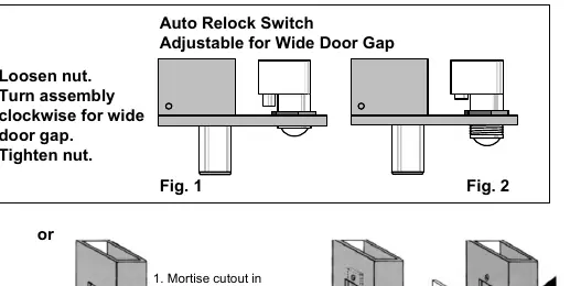
- Loosen the nut on the switch assembly.
- Turn the assembly clockwise until the proper adjustment is reached.
- Tighten the nut to secure the setting.
Wiring
The SDC PR-1000 Power Regulator is included with the bolt lock. It is recommended to use this regulator to reduce power consumption and heat, which increases the life of the solenoid.
- Without PR-1000: Connect DC power input directly to the solenoid leads.
- With PR-1000 (Recommended): Follow the wiring diagram to connect the PR-1000 between the power source and the lock.
Solenoid Voltage Configuration:
- 12VDC: .9 Amp (max)
- 24VDC: .45 Amp (max)
Troubleshooting
- Bolt does not project: Check voltage and alignment of the strike.
- Bolt projects but chatters: Voltage is too low.
- Bolt will not retract: Strike is misaligned.
Practical help
Common problems
Bolt does not project
Check voltage and alignment of the strike plate.
Bolt projects but chatters
Voltage is too low; ensure proper power supply.
Bolt will not retract
The strike is misaligned; adjust the strike plate position.
Before use
- Verify the door header or jamb has sufficient space for the lock and strike.
- Ensure the power supply matches the solenoid configuration (12VDC or 24VDC).
- Use the included PR-1000 Power Regulator to reduce heat and extend solenoid life.
- Check that the strike plate is properly aligned with the bolt.
- Ensure the automatic relock switch is adjusted for the specific door gap.
Specs in practice
- Continuous Duty
- The solenoid is rated to be powered continuously, though heat reduction is recommended.
Images and diagrams
- The installation diagram illustrates the 4-step process: mortising, attaching tabs, connecting wiring, and sliding the lock into place.
- The Auto Relock Switch diagram shows how to loosen the nut and rotate the assembly clockwise to compensate for wider door gaps.
Model compatibility
- PR-1000 Power Regulator is included and recommended for optimal performance.
- Optional Bolt Position Sensor (BPS) and Door Position Switch (DPS) are available for monitoring.

Manual page author
Emily Carter
User documentation editor
Prepares concise manual descriptions and highlights the most useful setup, operation, and maintenance information for readers.