Electronics / Cables & Adapters
User Manual for Sealevel SeaLINK+232.PC Serial Interface Adapter
Quick guide for the Sealevel SeaLINK+232.PC USB to RS-232 serial adapter. Includes installation steps, technical specifications, pinout diagrams, and troubleshooting tips.
Quick answers from the manual
Quick answer
- The SeaLINK+232.PC is a USB to RS-232 serial adapter for internal PC mounting. Always install the software drivers before connecting the hardware to a USB port. p. 3, 6, 7
Key actions
- Install software drivers p. 6
- Perform physical installation p. 7
Problems and fixes
Adapter not working
Check BIOS USB support, ensure drivers are installed, and use WinSSD for diagnostics.
p. 11Show 2 more answers Show less
Technical specifications
| Parameter | Value | Meaning | Pages |
|---|---|---|---|
| Power Requirements | +5VDC @ 50 mA | Power consumption | p. 10 |
| Operating Temperature | 0°C to 70°C | Operating range | p. 10 |
| Dimensions | 2.578" x 1.310" | Physical size excluding bracket | p. 10 |
Where to find it in the PDF
- Installation p. 6, 7
- Specifications p. 10
Table of contents
Manual images
Click an image to enlargeQuick Guide
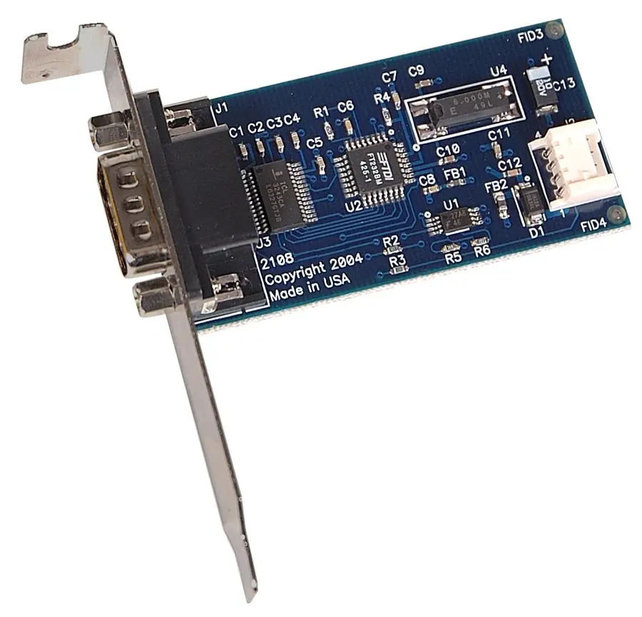
The Sealevel SeaLINK+232.PC is a USB to RS-232 asynchronous serial adapter designed for internal mounting within a PC chassis. It eliminates the need for external converters by connecting directly to the motherboard's USB header. Important: Do not connect the device to a USB port until the software drivers have been fully installed.
Software Installation
Before installing the hardware, you must install the necessary drivers:
- Locate and install the correct software from the Sealevel software driver database.
- Select the specific Part Number for your device during the installation process.
- If a warning regarding "Authenticode signature not found" appears, select 'Yes' to proceed; this is a standard OS notification and will not harm your system.
- Windows NT is not supported as it is not USB aware.
Physical Installation
Once the software is installed, you can proceed with the physical installation:
- The adapter is designed to be installed in any spare bracket location within the computer chassis.
- Connect the included 14” USB header cable (Item# CA260) to an available USB box header connector on the motherboard.
- Upon connection, the system should detect the new hardware. You can verify the installation in the Device Manager under the Ports (COM & LPT) class.
- Use the Sealevel WinSSD diagnostic utility to verify operation.
Technical Specifications
The SeaLINK+232.PC utilizes a USB UART with a 128-byte TX buffer and 384-byte RX buffer.
- Power Requirements: +5VDC @ 50 mA
- Operating Temperature: 0°C to 70°C (32°F to 158°F)
- Storage Temperature: -50°C to 105°C (-58°F to 221°F)
- Dimensions (excluding bracket): 2.578" x 1.310"
- Data Rates: Up to 460.8K baud
Troubleshooting
If you encounter issues, follow these steps:
- Ensure USB support is enabled in the System BIOS.
- Verify that the Sealevel software is correctly installed.
- Use the WinSSD utility and the supplied loopback plug to test communications. If the test transmits and receives the HEX pattern 55AA and an ASCII string, the adapter is functioning correctly.
- For further assistance, contact Sealevel Technical Support at 864-843-4343 or email [email protected].
Practical help
Common problems
Adapter not recognized by the system
Check that USB support is enabled in the System BIOS and that the Sealevel drivers are installed.
Driver signature warning during installation
Select 'Yes' to continue; the operating system is simply unaware of the driver, and it will not harm your system.
Communication failure
Use the WinSSD utility and a loopback plug to test the TD and RD lines.
Before use
- Verify USB support is enabled in the System BIOS
- Install software drivers before connecting the hardware
- Ensure a spare bracket location is available in the PC chassis
- Have the adapter ready for diagnostic testing if needed
Show more Show less
Specs in practice
- Operating Temperature
- 0°C to 70°C
Images and diagrams
- The PCB layout diagram shows the component placement and physical dimensions.
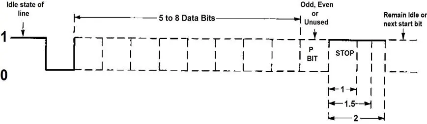
- The asynchronous communication diagram illustrates data framing, including start/stop bits and parity.
Model compatibility
- Compatible with Windows 98/ME/2000/XP
- Not compatible with Windows NT

Manual page author
David Miller
Documentation analyst