Computers / PC Components
User Manual for Sealevel 7204 ULTRA 485+2.PCI Serial Interface
Comprehensive user guide for the Sealevel 7204 ULTRA 485+2.PCI serial interface card. Includes hardware installation steps, jumper configuration for RS-422/485 modes, line termination, clock settings, and troubleshooting procedures.
Quick answers from the manual
Quick answer
- The Sealevel 7204 ULTRA 485+2.PCI is a two-channel PCI serial I/O adapter supporting RS-422 and RS-485 modes. It features field-selectable jumpers for mode configuration, line termination, and clock speeds. p. 3
Key actions
- Install the card p. 12
- Configure RS-485 mode p. 6, 7
Problems and fixes
Polling inefficiency
Use the Interrupt Status Port (ISP) at Base+7 to poll a single port for pending interrupts.
p. 14Technical specifications
| Parameter | Value | Meaning | Pages |
|---|---|---|---|
| Operating Temperature | 0° to 50°C | Operating range | p. 15 |
| Max Data Rate | 460.8K bps | Maximum supported baud rate | p. 3, 9 |
Where to find it in the PDF
- Card Setup p. 6, 7, 8, 9
- Installation p. 12
Table of contents
Manual images
Click an image to enlargeQuick Guide from the Manual
The Sealevel 7204 ULTRA 485+2.PCI is a two-channel PCI bus serial I/O adapter featuring the 16850 advanced UART. It supports field-selectable RS-422 and RS-485 serial ports with data rates up to 460.8K bps. The card is designed for industrial automation and control applications.
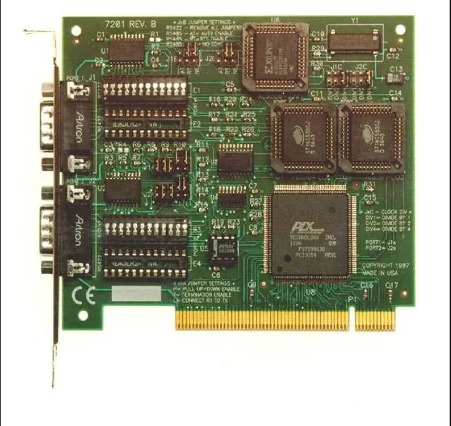
Card Setup and Jumper Configuration
The card uses jumper blocks to configure port settings. J1x refers to Port 1 and J2x refers to Port 2.
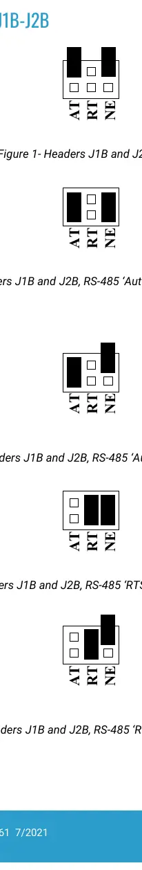

RS-485 Enable Modes (J1B, J2B)
- RTS Enable (RT): Uses the RTS modem control signal to enable the RS-485 interface.
- Auto Enable (AT): Automatically enables/disables the RS-485 interface without special software.
- Echo/No Echo (NE): Position 3 controls the receiver circuit. Select 'NE' for No Echo mode to prevent the system from receiving transmitted characters.
Line Termination (J1A, J2A)
For RS-485 networks, the boards at each end of the bus should have termination enabled.
- P: Adds/removes 1K ohm pull-down/pull-up resistors.
- T: Adds/removes 120-ohm line termination.
- L: Connects TX to RX for two-wire RS-485 operation.
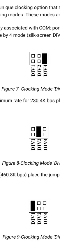
Clock Modes (J1C-J4C)
Select the clocking mode to adjust baud rates:
- Divide by 4 (DIV4): Standard COM port rates (up to 115.2K bps).
- Divide by 2 (DIV2): Up to 230.4K bps.
- Divide by 1 (DIV1): Maximum data rate (460.8K bps).
Installation
- Turn off PC power and disconnect the power cord.
- Remove the PC case cover.
- Locate an available PCI slot and remove the blank metal slot cover.
- Gently insert the ULTRA 485+2.PCI into the slot, ensuring it is seated properly.
- Secure the card with the screw.
- Replace the cover and reconnect the power cord.
- Install the appropriate software drivers from the Sealevel software driver database.
Technical Description
The card utilizes the 16850 UART with a 128-byte FIFO to reduce processor overhead. The Interrupt Status Port (ISP) at Base+7 allows software to poll a single port to determine if an interrupt is pending, improving efficiency over traditional polling methods.
Troubleshooting
If you encounter issues, use the Sealevel diagnostic software ('SSD' for DOS/Windows 3.x or 'WinSSD' for Windows 95/NT) to verify port functionality. Ensure there are no I/O address or IRQ conflicts with other installed hardware.
Practical help
Common problems
Card not detected or configuration conflict
Check for I/O address conflicts with other installed hardware. Ensure the card is securely seated in the PCI slot.
Communication errors in RS-485 mode
Verify jumper settings for RS-485 mode (RTS/Auto) and ensure proper line termination (120-ohm) is applied at both ends of the bus.
Incorrect baud rates
Check jumper settings on J1C-J4C for clock modes (Divide by 1, 2, or 4) to match your required data rate.
Before use
- Verify the card is securely seated in the PCI slot.
- Configure jumpers for the desired RS-422/485 mode.
- Ensure line termination is set correctly if using RS-485.
- Install the appropriate drivers from the Sealevel software database.
Images and diagrams
- J1B/J2B: Controls RS-485 mode (RTS/Auto) and Echo/No Echo.
- J1A/J2A: Controls line termination (120-ohm) and pull-up/down resistors.
- J1C-J4C: Controls clock modes (Divide by 1, 2, 4).
Model compatibility
- Compatible with PC and compatibles.
- RS-485 mode allows up to 31 devices per port.
- RS-422 mode supports cable lengths up to 4000ft.

Manual page author
Emily Carter
User documentation editor
Prepares concise manual descriptions and highlights the most useful setup, operation, and maintenance information for readers.