Tools / Automotive Tools
User Manual for Sealey PP100.V2 Automotive Probe
Quick guide for the Sealey PP100.V2 Automotive Probe. Learn how to perform voltage, polarity, continuity, and signal circuit tests, activate components, and replace the power switch.
Table of contents
Manual images
Click an image to enlargeQuick guide from the manual
The Sealey PP100.V2 is an advanced automotive probe designed for diagnostics, including short circuit finding, voltage testing, and component activation. Before use, ensure you are working with 2V-24V DC systems only. Always check vehicle service manuals before disconnecting any electrical sub-systems, especially those sensitive to voltage pulses like airbags or electronic control modules. The tool features a built-in circuit breaker (8A max) to protect against overloads.
Device overview
The probe consists of several key components:
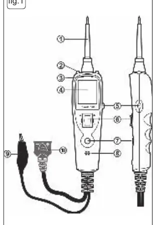
- Probe Tip: Contacts the circuit or component to be tested.
- Work Lights: Illuminate the work area.
- Red/Green Polarity Indicator: Identifies positive (red) or negative (green) circuits.
- LCD Display: Shows voltage, frequency, duty cycle, or resistance.
- Power Switch: Used to activate components with positive or negative battery current.
- Mode Button: Selects between DC voltage, scope, resistance, and audible indicator modes.
- Auxiliary Ground Lead: Used for continuity testing and component activation.
Basic connections and self-test
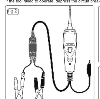
To connect the tool, unroll the probe cable and connect the red battery clip to the positive terminal and the black clip to the negative terminal of the vehicle battery. Alternatively, use the 12V vehicle accessory socket adaptor. Upon connection, the probe enters voltage mode and the work lights switch on. Perform a quick self-test by pressing the power switch forward (positive voltage, red LED) and rearward (negative voltage, green LED). If the tool fails to operate, press the circuit breaker reset button on the side of the housing.
Operating modes
The tool offers several modes accessible via the Mode Button:
- Voltage: Displays circuit voltage to the nearest 0.1V.
- Scope: Displays maximum/minimum voltage, frequency, and duty cycle. The display automatically adjusts the Y-axis scale.
- Resistance: Measures resistance between the probe tip and the auxiliary ground lead.
- Audible Indicator: Can be toggled on or off by pressing and holding the mode button.
Testing procedures
The probe is versatile for various automotive tasks:
- Voltage and Polarity Test: Contacts a positive circuit (red LED) or negative circuit (green LED).
- Continuity Testing: Use resistance mode. A reading of 0.0Ω indicates continuity.
- Signal Circuit Testing: Use scope mode to test sensors or components where a Diagnostic Trouble Code (DTC) has been detected.
- Activating Components: Connect the auxiliary earth lead to the component's negative terminal and touch the probe to the positive terminal. Use the power switch to energize the component.
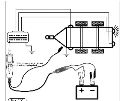
- Trailer Lights: Connect to the trailer battery, clip the auxiliary earth to the chassis, and probe the trailer socket contacts while using the power switch.
- Short Circuits: Remove the blown fuse and probe the fuse contacts. The contact that trips the circuit breaker identifies the shorted circuit.
Maintenance
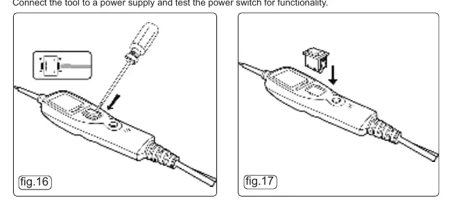
The power switch may deteriorate over time. Replacement switches are available through Sealey stockists. To replace, carefully prise the worn switch from the main casing and press the new one into place until it locks. Always test the switch functionality after replacement.
Specifications
- DC Voltage: 0-30V
- Frequency: 0-10KHz
- Duty Cycle: 1-99%
- Resistance: 50Ω-199kΩ
- Continuity Test: Audible if <50Ω
- Max Current: 8Amps
Manufacturer information
Sealey Group
Practical help
Common problems
Circuit breaker trips
Indicates an overload or short circuit. Reset using the button on the side of the housing.
No LED illumination
Check if the circuit is open or if the voltage is outside the ±0.8V range of the supply battery voltage.
Tool fails to operate
Ensure battery clips are securely connected or reset the circuit breaker.
Before use
- Check vehicle electrical wiring and disconnect sensitive components (e.g., airbags) if necessary.
- Ensure battery clips are connected to the correct terminals (Red to Positive, Black to Negative).
- Perform a quick self-test by activating the power switch forward and rearward.
- Verify the tool is in the correct mode (Voltage, Scope, or Resistance).
Specs in practice
- Continuity Test
- Audible tone sounds if resistance is less than 50Ω.
Images and diagrams
- Fig 1: Device components including probe tip, work lights, LCD, and power switch.
- Fig 2: Basic battery connection setup.
- Fig 16-17: Power switch replacement procedure.
Model compatibility
- For use with 2V - 24V DC systems only.
- Do not use on AC lines or vehicle ignition systems.

Manual page author
Emily Carter
User documentation editor
Prepares concise manual descriptions and highlights the most useful setup, operation, and maintenance information for readers.