Tools / Automotive Tools
Sealey VSE5951.V2 Timing Tool Kit User Manual
Quick guide for the Sealey VSE5951.V2 Timing Tool Kit. Includes instructions for engine timing, belt replacement, crankshaft and camshaft locking procedures for VAG, Ford, Dodge, and Mitsubishi diesel engines.
Table of contents
Manual images
Click an image to enlargeQuick Guide from the Manual
The Sealey VSE5951.V2 Timing Tool Kit is designed for engine timing and belt replacement on a wide range of VAG Pumpe Duse and Common Rail diesel engines, as well as specific Ford, Dodge, and Mitsubishi models. This kit includes various locking tools for crankshafts and camshafts, and tensioner adjustment tools. Always refer to the vehicle manufacturer's service data for specific procedures and data.
Safety Information
- Wear approved eye protection and appropriate Personal Protective Equipment (PPE).
- Ensure the vehicle is adequately supported by axle stands if raised by a jack.
- Do not use damaged tools.
- Incorrect or out-of-phase camshaft timing can cause engine damage (contact between valve head and piston crown).
- Always account for all tools and components; do not leave them in or near the engine.
Product Overview
The kit contains a comprehensive selection of tools, including:
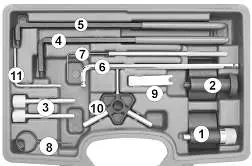
- Crankshaft locking tools (for both oval and round gears).
- Camshaft locking pins.
- Tensioner adjustment and locking tools.
- Auxiliary belt locking pin.
Operating Instructions
Crankshaft Timing
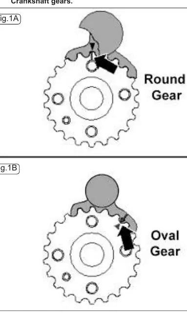
There are two types of crankshaft gears: 'round' and 'oval'. It is critical to select the correct locking tool from the kit. The crankshaft must be positioned at Top Dead Center (TDC) before fitting the tool. The tool is fitted by sliding it into the gear teeth from the front face.
Camshaft Timing
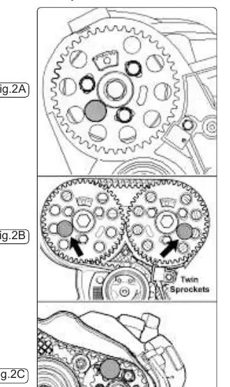
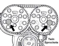
Timing is correct when gear windows are at the top and timing marks are aligned. Locking pins are inserted through the sprocket and sprocket hub into the timing hole in the cylinder head. For twin camshaft engines, pins are inserted into both sprockets.
Belt Tensioners
The kit includes tools for both hydraulic and mechanical (friction dampened) tensioners. For hydraulic tensioners, specific set pins (4mm, 7mm, 8mm) are used to set the gap. For mechanical tensioners, the adjuster is used to turn the eccentric until the locking pin can be inserted or removed.
Timing Belt Installation (Common Rail)
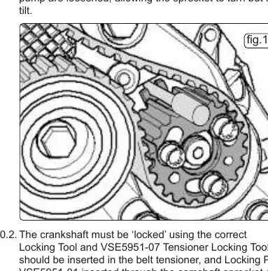
- Loosen the 3 bolts on the camshaft sprocket and the 3 bolts on the HP pump to allow the sprockets to turn without tilting.
- Lock the crankshaft using the correct tool and insert the tensioner locking tool.
- Fit the new belt in order: crankshaft gear, tensioner, camshaft sprocket, coolant pump sprocket, HP pump sprocket, and idler roller.
- Release the tensioner and apply pressure to the camshaft sprocket in an anticlockwise direction to maintain tension while tightening the bolts.
- Remove all tools, turn the engine over twice by hand, and return to TDC No.1 cylinder to verify timing.
Adjusting Timing
If the locking pin cannot be inserted easily, timing adjustment is required. This involves loosening the sprocket bolts, turning the crankshaft or sprocket as specified for the engine type (8v or 16v), and re-tightening the bolts while holding the sprocket with a suitable holding tool. Always use new sprocket bolts when performing these procedures.
Manufacturer information
Sealey Group
Practical help
Common problems
Locking pin cannot be inserted
Timing adjustment is necessary. Follow the specific procedure for your engine type (8v or 16v) to align the sprocket and locking hole.
Crankshaft locking tool does not fit
Ensure the crankshaft is at TDC No.1 cylinder and that you have selected the correct tool for your gear type (round vs oval).
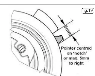
Tensioner pointer not aligned
Ensure the pointer is centered or a maximum of 5mm to the right of the notch on the back plate.
Before use
- Verify the engine code matches the application list in the manual.
- Identify if the engine uses 'round' or 'oval' crankshaft gears.
- Ensure you have the correct locking tools for your specific engine variant.
- Wear approved eye protection and appropriate PPE.
- Have a suitable holding tool for the camshaft sprocket.
Specs in practice
- Elongated holes
- Slots in sprockets that allow for minor timing adjustments.
Images and diagrams
- Fig 1A/1B: Shows the difference between round and oval crankshaft gears.
- Fig 2A/2B/2C: Illustrates camshaft locking pin placement for single, twin, and CR sprockets.
- Fig 19/22: Shows the correct tensioner pointer alignment relative to the notch.
Model compatibility
- Compatible with VAG, Ford, Dodge, and Mitsubishi diesel engines.
- Covers 1.2D, 1.4D, 1.6D, 1.9D, and 2.0D engines.
- Requires VSE5852 'Service Position' Front End Support Guide Set for some VAG models.

Manual page author
David Miller
Documentation analyst
Organizes user manual content into clear summaries, with attention to model details, product context, and everyday usability.