HVAC / Compressor Controllers
Secop 105N4100 Controller Instructions
Quick guide for the Secop 105N4100 controller for NLV compressors. Includes wiring diagrams, installation requirements, airflow specifications, and safety guidelines for R290 service.
Table of contents
Manual images
Click an image to enlargeImportant Information
This document provides essential instructions for the installation and operation of the Secop 105N4100 controller used with NLV compressors. Users must ensure proper electrical connections and maintain adequate airflow to prevent overheating and ensure system longevity. Always adhere to safety protocols when handling R290 refrigerant systems.
Wiring and Electrical Connections
The controller requires a 115V (50/60Hz) power supply. Ensure all connections are secure and follow the wiring diagram provided in the manual. Key connection points include:
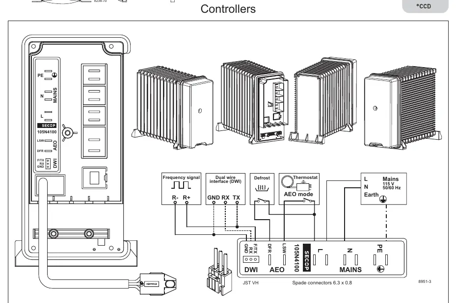
- Mains: Connect L (Line), N (Neutral), and Earth (PE) to the designated terminals.
- DWI (Dual Wire Interface): Connect GND, RX, and TX pins as required.
- Control Inputs: Terminals are provided for Frequency signal, Defrost, Thermostat, and AEO mode.
- Connectors: Use spade connectors 6.3 x 0.8 or JST VH connectors as specified in the wiring diagram.
Installation and Airflow Requirements
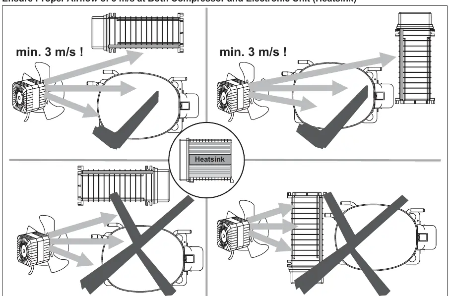
Proper cooling is critical for the operation of the compressor and the electronic unit. You must ensure a minimum airflow of 3 m/s directed at both the compressor and the heatsink. Failure to maintain this airflow can lead to overheating and system failure.
Service and Safety Precautions
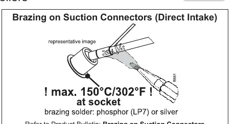
When performing service or repairs on systems using R290 refrigerant, strictly follow safety guidelines. When brazing on suction connectors (Direct Intake), do not exceed a maximum temperature of 150°C (302°F) at the socket. Use phosphor (LP7) or silver brazing solder. Refer to the specific Product Bulletin: Brazing on Suction Connectors for detailed procedures.
Technical Specifications
- Supply Voltage: 115 V (± 10%)
- Frequency: 50/60 Hz
- Max Input Power: 1000 W
- Operating Conditions: +5 °C to +43 °C (humidity < 90% rH non-condensing)
- Storage Conditions: -25 °C to +70 °C (humidity < 90% rH non-condensing)
Practical help
Common problems
System overheating
Ensure a minimum airflow of 3 m/s is directed at both the compressor and the heatsink.
Damage during brazing
Do not exceed 150°C (302°F) at the socket when brazing suction connectors.
Before use
- Verify supply voltage is 115V (± 10%).
- Ensure ambient temperature is within the operating range of +5°C to +43°C.
- Confirm that the installation location allows for at least 3 m/s airflow.
- Check all wiring connections (Mains, Thermostat, Defrost, DWI) against the diagram.
- Ensure proper grounding (PE) is connected.
Specs in practice
- Supply voltage
- 115 V (± 10%) required for operation.
- Max input power
- 1000 W maximum power consumption.
Images and diagrams
- The wiring diagram illustrates the connection points for Mains, Thermostat, Defrost, DWI, and Frequency signal inputs.
- The airflow diagram demonstrates the required direction and velocity of air over the compressor and heatsink components.
Model compatibility
- Designed for use with Secop NLV Compressors.

Manual page author
David Miller
Documentation analyst
Organizes user manual content into clear summaries, with attention to model details, product context, and everyday usability.